Why not actually see that the thing oscillates, you have access to a scope? I wouldn'tt do as 1n and remove all those "excess parts"
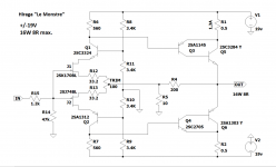
Balanced topologies have high PSRR. I had Q2/Q4 in mind that are critical to stability, but you have the very nice Hitachi devices. (Q1/Q5 are common base amplifiers). Everything looks fine, in fact, "perfect" so there is no need to replace anything. Now I am not sure what to think, unfortunately, we are not closer to the solution...
I use the same PCB with very good results. In case of occilation it is possible to reduce the bandwith of the amplifier by adding one capacitor 4.7 to 10 nF in paralell to the 220 NF resistor. I use 4 of this amplifier with slightly different PCB layout, but always with this capacitor.
good luck
Helmut
good luck
Helmut
High frequency oscillation (in the Mhz region) is cured by adding base resistor but you probably can`t do that conveniently. It is untechnical not to use base/gate resistor on the output devices.
I use the same supply voltage, but I added 33R resistors to the source of the jfet. The BL version of jfet requires a little change to make the current through them match the original version. A supply voltage of +/- 19V needs a little more modification, first with 1R in the output collectors it is impossible to get 16W power because you need to increase the current through the output, and then that 1R will be too much, with them you need to change the resistors in the collectors in a cascade. My output transistors have a high Ft, at 2A almost 80MHz and I don't have any problems in the operation of the amplifier especially with the oscillations and I don't have any capacitor via the resistors in the feedback. I made my own PCBs.
Attachments
Some of those semis are long obsolete and if genuine OEM parts, they're probably pulled from equally old, discarded gear. I would be testing semis that aren't shiny, straight leaded and obviously brand new but also, those that are known to be long obsolete from the manufacturer's records, datasheets etc. but somehow, appear to be brand new. Maybe that's because they are recently manufactured "copies" or re-marked substitutes?
Jim's audio is one of the long-time reputable Ebay kits and parts suppliers so I don't suggest he has had anything to do with this but there could be others in his supply chain who haven't checked their sources well enough.
As the fault is only in one channel, the possibilites are narrowed to components and soldering as the likely culprits but that could mean thorough testing with at least a component tester and the low resistance range or the continuity test on your DMM.
Perhaps discussion at Zen Mod, I built the oscillation detector, question: could help confirm suspicion of oscillation?
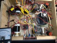
How are transistor temperatures compared between L/R board? Any excessive heating anywhere?
Wow, now I'm spoilt, so many of you guys commenting! Thanks.
Will try to respond to all.
Temperatures consistent across channels and + and - rail regulators.
Balanced topologies have high PSRR. I had Q2/Q4 in mind that are critical to stability, but you have the very nice Hitachi devices. (Q1/Q5 are common base amplifiers). Everything looks fine, in fact, "perfect" so there is no need to replace anything. Now I am not sure what to think, unfortunately, we are not closer to the solution...
Thanks.
So it has a high PSRR? I thought low rail voltages said no.
Anyway, no problem, but I no longer have an explanation as to why it sounds better to my ear with the REGS. Without regs there is more power more dynamics. But sacrifice a bit of that with regs and the midrange tends to sublime. ie magic good. I have local quite respected audio guys who have heard this amp and love it. Ask me to build them one! No time thanks 😉
I use the same PCB with very good results. In case of occilation it is possible to reduce the bandwith of the amplifier by adding one capacitor 4.7 to 10 nF in paralell to the 220 NF resistor. I use 4 of this amplifier with slightly different PCB layout, but always with this capacitor.
good luck
Helmut
thanks for this awesome tip!
I think I have it under control, will explain later.
I use the same supply voltage, but I added 33R resistors to the source of the jfet. The BL version of jfet requires a little change to make the current through them match the original version. A supply voltage of +/- 19V needs a little more modification, first with 1R in the output collectors it is impossible to get 16W power because you need to increase the current through the output, and then that 1R will be too much, with them you need to change the resistors in the collectors in a cascade. My output transistors have a high Ft, at 2A almost 80MHz and I don't have any problems in the operation of the amplifier especially with the oscillations and I don't have any capacitor via the resistors in the feedback. I made my own PCBs.
Awesome so source resistors on the FETS a good idea.
Actually a little more detail here on mine.
I modded it to get more power.
So I have altered the bias to have steady state current at 1.3 amp.
Have not changed power collector R's. Still have 1 ohm.
Have upped the power tranny to 500VA and after regulation I have + - 23 volts about. I figure the amp does up to 25 Watts now.
It does sound good. As said audio mates comments are amazement.
Is it the same boards as mine?
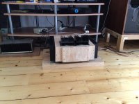
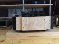
I use it on daily basis, and it has become my best amp, unfortunately still no chassis.
different board. pics to come.
Ok so so far I have tried the first idea before all these great suggestions.
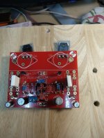
I looked at the FB resistor 250 ohm, and noticed that the 30W hiraga boards used a 300ohm. Since I upped my power I thought lets try it. So on the bad board I upped to 300 ohm.
After 24 hrs of testing it somehow seems to have done the trick!
I haven't had to do the reset procedure at all to rescue gain.
And the amp sounds noticeably improved. I guess it's not wasting power in one channel in the ultra soncic regions. It seems a great result, but it might take a couple of weeks to be sure.
Why did it perhaps work? I am not sure. A bigger FB R means less general feedback if I am right. Because the volts divider with the 10R to earth means less volts feeding back. I guess if there is in phase stuff going through there then less in phase feedback would contribute less to oscillation. But then I admit confusion because I also know that a 3nf cap across the FB R would make a short circuit feedback at high frequencies. Which is more feedback and if in phase would contribute to instability. Perhaps the instability is only 30Khz and this makes a difference then. I probably do need to put a scope on the output and have a look, but now it may be fixed.
Will try to send some pics.
And THANKS.
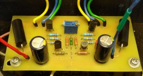
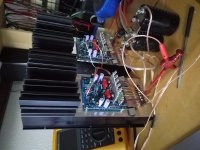
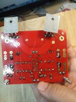
Attachments
-
 134072206_1459299677602813_6190304860849239799_n.jpg343.8 KB · Views: 153
 -
 134280843_228129908875775_2828742491732379078_n.jpg501.2 KB · Views: 136
 -
 134662533_404840407449850_8948232170847694235_n.jpg354.1 KB · Views: 129
 -
 134835062_2931601173742718_5812992347351046820_n.jpg368.4 KB · Views: 127
 -
 135827351_265973148293649_315034030408756395_n.jpg398.1 KB · Views: 130
You're lucky! The first one I built (from the Audiophile kit) went DC and killed a JBL woofer. My fault, I had used a transformer slightly higher voltage and maybe didn't compensate on the bias. Blew the output transistors, likely from over heating. 🙁I don't even bother dc protection with a Hiraga, as the design needs no such.
- Home
- Amplifiers
- Solid State
- Problem with an Hiraga amp.