Yeah, sorry I've been away so long 😱 ..
I, too, have worried about the switchover thing since you first mentioned dual-preamps -- but didn't want to undertake the complexity of electronic switching.
Can we get back to the bias issue for just a minute? I was just so sure that I'd be able to score some '5457s to test the idea, but alas the miracle has not come true. What I'd like to try is replacing R1 (the lower resistor in the bias divider) with a small signal diode; then raising R2 to 680 or 820k. (You could even use a 1M if that's all you have handy.) That will help maintain performance as the battery voltage drops. Granted, we haven't addressed the issue before -- sorry 😱.
Then we'll judge from the resulting voltages what Source resistor value to fit. And don't worry -- there's a sweet spot between heavy current draw and poor dynamic range.
The preamp switching thumps bring a whole new round of design nightmares. A DPDT center-off switch leaves at least one issue unsolved. You can keep the Off preamp from wasting power; then choose between selecting either outputs or inputs. But the one left unselected will need careful design -- and probably mods -- to avoid loading by the unpowered circuit.
I have to ask -- are you absolutely certain that the two preamps are sufficiently different sounding, that you'll want to flip back and forth during a tune? Because if they sound that different, we've probably messed up something in the design!😉
Although a subminiature center-off 3PDT isn't impossible to find, it won't solve the thump problem. For that the best, and possibly only, solution is electronic switching. Consider two momentary pushbuttons, each selecting one preamp; they're exclusive-OR'd so whichever one you tapped last, stays on. When a 'state change' happens, a monostable briefly pulses a shunt-mute to 'zero' the coupling capacitor(s). Unplugging the cable to the amp turns off both.
It'll probably take more design than you're comfortable with, but it's only slightly more complicated than some of the dual-supply solutions we touched on earlier. I'll give it some hard thinkin', but will be kind of surprised if you're really ready to undertake it. It would make more sense to me to devise a mechanical interlock -- maybe with the section of faceplate that the tone pots occupy -- 5 seconds swap-out-and-in. Easy to execute between songs without too much fuss.
Cheers
edit: forgot to answer the 'capacitor in series with the supply' question: won't work - supply is DC which can't get through a capacitor
and: questions are good -- forget the shame-business 😉
Last edited:
Ok, no cap in series.A capacitor in series with a DC voltage source will eventually (after it is charged) shut down the supply completely.
Why don't you use a TRS type phone socket in your guitar with the negative battery lead connected to the ring lug? This also avoids the possibility that your batteries are getting discharged it you forget to trip the on-off switch.
And it's always been good practice to first plug the cord into the guitar, then connect it to the amp. Otherwise you may get nasty noise even with a passive, unpowered instrument.
Best regards!
I have the jack power on when a cable is plugged in, but that's the main "switch". After that, I need to switch the power between the 2 preamps depending which is in use. That's when the thump comes up. Powering both preamps at the same time and switching outputs only won't create loud clicks but is a battery waste.
I, too, have worried about the switchover thing since you first mentioned dual-preamps -- but didn't want to undertake the complexity of electronic switching.
Consider two momentary pushbuttons, each selecting one preamp; they're exclusive-OR'd so whichever one you tapped last, stays on...
It'll probably take more design than you're comfortable with, but it's only slightly more complicated than some of the dual-supply solutions we touched on earlier. I'll give it some hard thinkin', but will be kind of surprised if you're really ready to undertake it...
If we come to a low enough power solution with this discrete preamp (let's say if we get less than 2mA for both preamps, that's about 0.8mA max for this one) probably the best solution would be to power them both at the same time all the time and switch the output only to avoid further complextion of the whole thing. It's fun project but I'm not sure i'd have the time to spend few more months on a switching circuit for usage in one bass. Thanks a lot for your thoughts on it! Let's see what's going to come out of this preamp and go from there.
I have to ask -- are you absolutely certain that the two preamps are sufficiently different sounding, that you'll want to flip back and forth during a tune? Because if they sound that different, we've probably messed up something in the design!😉
Well.. haha, the difference isn't dramatic and I think we did a really good job on the preamps. I don't think i would switch during a tune, but whenever it is chances are you will forget to lower amp's volume before switching and there goes a loud thump... and on high volume it will be LOUD ��. Plus, the DPDT push/pull is on the volume pot on the bass.
The way i hear it, the difference comes from the different tone circuits. The opamp one with Baxandall, sounds more natural, transparent and smoother, and has cut. While this one - the Fender tone, is boost only, has steeper curves and mid scoop which affects the frequencies just differently enough to give the sound different signature when boosted, the more boosted the more obvious the difference. The difference is probably easier to hear on a "Hi-Fi" open and bright pickup, as the one i use, but it would be likely way less different between the two preamps on most other pickups that aren't so "Hi-Fi" sounding.
Can we get back to the bias issue for just a minute? I was just so sure that I'd be able to score some '5457s to test the idea, but alas the miracle has not come true. What I'd like to try is replacing R1 (the lower resistor in the bias divider) with a small signal diode; then raising R2 to 680 or 820k. (You could even use a 1M if that's all you have handy.) That will help maintain performance as the battery voltage drops.
Then we'll judge from the resulting voltages what Source resistor value to fit. And don't worry -- there's a sweet spot between heavy current draw and poor dynamic range.
I need some clarification on this. You're suggesting to replace the bias trimpot (which is the lower resistor - R2) with a resistor 680k-1M, and put switching diode in the place of 100k (upper resistor - R1), or the other way around? I guess the orientation of the diode should follow battery polarity - positive on diode to +18V line? Can I use BAS16HT1G diode? That's what I have on hand, i've used it for reverse polarity protection in the same circuit.
edit: forgot to answer the 'capacitor in series with the supply' question: won't work - supply is DC which can't get through a capacitor
and: questions are good -- forget the shame-business 😉
Ok, no cap in series 🙂
Last edited:
Right. So, how resistant are you to the electronic switching idea? It'll probably be another little PCB (or possibly could be hand wired on perf-board or Vero board) with almost the same or a little less complexity. Do the preamps really sound all that different? And, are you sure the dual-loading of the pickup isn't causing an issue? Only asking because unpowered semiconductor circuits usually present highly nonlinear loads.
Also still need a firm answer to the, 'How often are you going to want to change preamps during a tune?' question.😉
Did you give a good think to the mechanical interlock idea?
Regards
edit: Darn it -- should've checked for your more recent post before submitting this; gimme a bit to catch up (in case you've already answered some of this ..) -- Sorry😱
Last edited:
Darn it .. Another 😱 .. I had the resistor component designations BACKwards on the 24Dec post! 😱😱
And I was so sure I had ascertained that on the Sep schematic. (Even have/had the JPG up where I COULD readily refer to it ..) 🙁
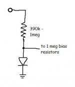
Your second notion is correct -- the diode will replace the trimpot, providing a low, somewhat temperature-compensated voltage for the bias point. The BAS16HT1G would be perfect (*1) for this task. Fit it Cathode-to-ground, and Anode to both of the 1M resistors going to the FET Gates, as well as to the high-value resistor (originally R1, 100k) providing its forward bias current. Anything from about 390k to 1meg will work, adding between 44 and 17uA respectively to the battery drain.
Attention Forum Gurus: I'm having trouble wrapping my brain around the temperature issue. The main object of replacing the lower divider resistor with a diode was to limit the bias variation as the battery voltage drops from 18 to ~14V. But somehow it seems like the diode's negative tempco might be the opposite of what the FET's would prefer. I'd welcome a second opinion.
Cheers
*1) however, the BAS16HT1G is not the best choice for polarity protection; though it will work OK, something heavier like a 1N4001 or '4004 would better withstand the capacitor charging surges
And I was so sure I had ascertained that on the Sep schematic. (Even have/had the JPG up where I COULD readily refer to it ..) 🙁
Your second notion is correct -- the diode will replace the trimpot, providing a low, somewhat temperature-compensated voltage for the bias point. The BAS16HT1G would be perfect (*1) for this task. Fit it Cathode-to-ground, and Anode to both of the 1M resistors going to the FET Gates, as well as to the high-value resistor (originally R1, 100k) providing its forward bias current. Anything from about 390k to 1meg will work, adding between 44 and 17uA respectively to the battery drain.
Attention Forum Gurus: I'm having trouble wrapping my brain around the temperature issue. The main object of replacing the lower divider resistor with a diode was to limit the bias variation as the battery voltage drops from 18 to ~14V. But somehow it seems like the diode's negative tempco might be the opposite of what the FET's would prefer. I'd welcome a second opinion.
Cheers
*1) however, the BAS16HT1G is not the best choice for polarity protection; though it will work OK, something heavier like a 1N4001 or '4004 would better withstand the capacitor charging surges
Attachments
It's all good Rick 🙂
Not too resistant to the electronic switching, if i can see the schematic and component sourcing it will be easier to make a decision on it. Do you have a schematic for it? Also we need to consider the power consumption of it too, it's the whole point on power switching in "live" mode.
The main sound difference is coming from the Tone circuit used in each when boosted, the Baxandall is more natural and transparent, while this one, Fender, has steeper curves and has this mid scoop that creates this another unique boost that differs from Baxandall. The difference is more obvious with more boost.
Probably not too often switching between the two, unlikely in mid tune, more likely between songs etc.
I haven't thought of mechanical interlocking, do we need it here?
Ok, will do it as in the image you attached, thanks for that 🙂. Good that the diode is a good fit for this.
Should we wait for a second opinion before we try this? Also, what source resistor values are we using with the diode in bias, 1k8 or 10k?
Couldn't find 1N400x small enough to fit existing 0805 component size, BAS16HT1G is small enough and has high reverse protection current for its size so i went with it, it's enough that it's "OK". Anyway it's hard to reverse battery polarity with two 9V batteries in series, they won't fit their slot so the diode is pretty much "just to be there". But thanks for the tip, good to know 🙂
Right. So, how resistant are you to the electronic switching idea? It'll probably be another little PCB (or possibly could be hand wired on perf-board or Vero board) with almost the same or a little less complexity. Do the preamps really sound all that different? And, are you sure the dual-loading of the pickup isn't causing an issue? Only asking because unpowered semiconductor circuits usually present highly nonlinear loads.
Not too resistant to the electronic switching, if i can see the schematic and component sourcing it will be easier to make a decision on it. Do you have a schematic for it? Also we need to consider the power consumption of it too, it's the whole point on power switching in "live" mode.
The main sound difference is coming from the Tone circuit used in each when boosted, the Baxandall is more natural and transparent, while this one, Fender, has steeper curves and has this mid scoop that creates this another unique boost that differs from Baxandall. The difference is more obvious with more boost.
Also still need a firm answer to the, 'How often are you going to want to change preamps during a tune?' question.😉
Did you give a good think to the mechanical interlock idea?
Probably not too often switching between the two, unlikely in mid tune, more likely between songs etc.
I haven't thought of mechanical interlocking, do we need it here?
Your second notion is correct -- the diode will replace the trimpot, providing a low, somewhat temperature-compensated voltage for the bias point. The BAS16HT1G would be perfect (*1) for this task. Fit it Cathode-to-ground, and Anode to both of the 1M resistors going to the FET Gates, as well as to the high-value resistor (originally R1, 100k) providing its forward bias current. Anything from about 390k to 1meg will work, adding between 44 and 17uA respectively to the battery drain.
Ok, will do it as in the image you attached, thanks for that 🙂. Good that the diode is a good fit for this.
Attention Forum Gurus: I'm having trouble wrapping my brain around the temperature issue. The main object of replacing the lower divider resistor with a diode was to limit the bias variation as the battery voltage drops from 18 to ~14V. But somehow it seems like the diode's negative tempco might be the opposite of what the FET's would prefer. I'd welcome a second opinion.
Should we wait for a second opinion before we try this? Also, what source resistor values are we using with the diode in bias, 1k8 or 10k?
*1) however, the BAS16HT1G is not the best choice for polarity protection; though it will work OK, something heavier like a 1N4001 or '4004 would better withstand the capacitor charging surges
Couldn't find 1N400x small enough to fit existing 0805 component size, BAS16HT1G is small enough and has high reverse protection current for its size so i went with it, it's enough that it's "OK". Anyway it's hard to reverse battery polarity with two 9V batteries in series, they won't fit their slot so the diode is pretty much "just to be there". But thanks for the tip, good to know 🙂
When you say, 'high reverse protection current', does that mean that you have it installed as a shunt? It's definitely too light for shunt duty; but as you say, connecting both 9V batteries in reverse almost couldn't happen accidentally.
The second opinion is only about whether the diode's smallish temperature coefficient will undermine the improvement in consistency of sound quality with falling battery voltage (that having the diode provides). No need to suspend progress for it. I hope you still have the 1k8's fitted; that would be the place to start. We'll need to confirm that the FET current is adequate at that bias voltage. In fact, it'd probably be smart to wire it using short jumpers to get the measurements -- in case two of the BAS16HT1G's in series may be needed.
'Mechanical interlock' -- was just a thought that floated by one late evening. As currently discussed, you don't need one. But it dawned on me that if you felt like cutting a new faceplate, you could duplicate a section of it, and make it 'plug-able' by mounting one preamp on each. It would be quite an extra bit of work, but there would be advantages: The appearance would be less cluttered with 3 knobs instead of 5; only one preamp at a time draining the battery is achieved; avoiding another long design-build-and-test cycle is certainly a plus; and the thump problem when changing becomes easier to manage. Of course, it would be slower to change than just throwing a switch! That's why I thought it would be worth a good 'hard think' about how quickly the change REALLY needed to be.
If we do undertake the design of electronic switching, there are a couple of caveats:
- It will take some (more!?😉) time -- it'd probably be a good idea to choose one of the preamps to live with for a while and put that beautiful ax to work.
- It may not be possible to achieve zero click/pop/thump with a short enough switchover (muted) time to use during a tune -- without, say, a quarter note rest or so.
Let's see if we can get the '5457-based preamp's current draw low enough to at least consider having them both powered on whenever the 1/4-phone jack is occupied.
Regards
Last edited:
When you say, 'high reverse protection current', does that mean that you have it installed as a shunt? It's definitely too light for shunt duty; but as you say, connecting both 9V batteries in reverse almost couldn't happen accidentally.
The diode is connected directly to the power supply (on PCB) - anode to GND, kathode to positive voltage. In the datasheet i think it said 20-30A reverse current load or something, that's what i meant by "high reverse current".
The second opinion is only about whether the diode's smallish temperature coefficient will undermine the improvement in consistency of sound quality with falling battery voltage (that having the diode provides). No need to suspend progress for it. I hope you still have the 1k8's fitted; that would be the place to start. We'll need to confirm that the FET current is adequate at that bias voltage. In fact, it'd probably be smart to wire it using short jumpers to get the measurements -- in case two of the BAS16HT1G's in series may be needed.
Ok, tried it with one diode and 1M resistor with 2x 1k8 fitted (no source caps), what i got is:
@18V
Total current consumption - 0.6mA (great value so far)
FET current - 0.3mA per FET
17.6uA through the diode
about 0.9-0.95 gain, just slightly less than unity
very slight distortion regardless of EQ boost level
'Mechanical interlock' -- was just a thought that floated by one late evening. As currently discussed, you don't need one. But it dawned on me that if you felt like cutting a new faceplate, you could duplicate a section of it, and make it 'plug-able' by mounting one preamp on each. It would be quite an extra bit of work, but there would be advantages: The appearance would be less cluttered with 3 knobs instead of 5; only one preamp at a time draining the battery is achieved; avoiding another long design-build-and-test cycle is certainly a plus; and the thump problem when changing becomes easier to manage. Of course, it would be slower to change than just throwing a switch! That's why I thought it would be worth a good 'hard think' about how quickly the change REALLY needed to be.
If we do undertake the design of electronic switching, there are a couple of caveats:
- It will take some (more!?😉) time -- it'd probably be a good idea to choose one of the preamps to live with for a while and put that beautiful ax to work.
- It may not be possible to achieve zero click/pop/thump with a short enough switchover (muted) time to use during a tune -- without, say, a quarter note rest or so.
In that case, I think mechanical interlock would be too much for this. I already have 4 pots, Vol, stacked EQ for this preamp, stacked EQ for the other one plus one more pot that acts as a "clarity" adjustment (probably closest description as to how it affects sound) which i accidentally discovered while playing with the other preamp's EQ (yeah i ended up playing even further with the other one and now have 3 trimpots on it which make the whole thing much more flexible to adjust the preamp by taste).
Electronic switching is still and a better option i think (maybe not needed if we keep the current low enough). Roughly, the length of the pop is probably less than 1/4s. So while switching muted state of 1/4 to 1/2s is totally fine. The less the better, but up to half a second sounds reasonable considering the length of the pop, also i don't think i will switch mid tune, mainly between songs when needed.
Let's see if we can get the '5457-based preamp's current draw low enough to at least consider having them both powered on whenever the 1/4-phone jack is occupied.
Well we got it to 0.6mA now, combined with the other at the same time is around 1.7-1.8mA total which actualy doesn't sound bad considering we have two preamps, which are high performance. I'm playing the opamp one alsmot every day and it's frickin' great.
Regarding the new bias divider: The measurements I'm most interested in, are the Drain voltages. Some fiddling is probably still in order.
Hoping you have only the terminology backwards on the bias diode -- the end with the 'Cathode band' needs to go to ground. We want a voltage a few hundred millivolts above ground; placed the other way, the Gate voltages will go almost all the way to the positive rail -- it wouldn't be working as well as it is if it was backwards.

More later -- a new idea occurs if the click/pop/thump only needs improvement, rather than complete elimination. Would be a much simpler circuit than full electronic supply switching.
Cheers
Hoping you have only the terminology backwards on the bias diode -- the end with the 'Cathode band' needs to go to ground. We want a voltage a few hundred millivolts above ground; placed the other way, the Gate voltages will go almost all the way to the positive rail -- it wouldn't be working as well as it is if it was backwards.
I'm playing the opamp one .. and it's frickin' great.
More later -- a new idea occurs if the click/pop/thump only needs improvement, rather than complete elimination. Would be a much simpler circuit than full electronic supply switching.
Cheers
Last edited:
to you for making it possible 🙂I'm most interested in, are the Drain voltages. Some fiddling is probably still in order.
Drain is 15V on both, sorry i missed that
Voltage on the diode is 414mV (measured directly on Cathode/GND and Anode)
Hoping you have only the terminology backwards on the bias diode -- the end with the 'Cathode band' needs to go to ground. We want a voltage a few hundred millivolts above ground; placed the other way, the Gate voltages will go almost all the way to the positive rail -- it wouldn't be working as well as it is if it was backwards.
Cathode (band/line on the diode side) is on the ground, Anode is on the 1M resistor, exactly as in the image you posted a few posts above.
More later -- a new idea occurs if the click/pop/thump only needs improvement, rather than complete elimination. Would be a much simpler circuit than full electronic supply switching.
I'm all ears, definitely an option
Still working -- hope to have something in a few hrs ..
Sorry about the *recriminations* on diode polarity -- my mistake aGAIN 😱 !
I misread your description concerning the reverse polarity protection diode, as I was thinking of the new bias diode arrangement! Sorry ..
Cheers
Sorry about the *recriminations* on diode polarity -- my mistake aGAIN 😱 !
I misread your description concerning the reverse polarity protection diode, as I was thinking of the new bias diode arrangement! Sorry ..
Cheers
Couple of questions:
- which supply lead are you planning on switching, B+ or ground?
- how comfortable are you with digital logic, say CMOS 4000B-series?
Sure woulda liked to have pulled off the idea from the other night (was pretty clever, IMHO😉), but it had bits that would need testing and I can't build it to prove it works. Also, I don't trust simulations for such irregular notions -- at least at my level of simulator-operating-expertise!
Regards
Last edited:
I've done some digital electronics very long time ago and IIRC think I used the 4000 series specifically, but it's been so long it's close to as if I've never done it. Not feeling uncomfortable to do it though.
Reminder on one very important thing related to this though, what would the power consumption be on this circuit? You know that the whole idea is to save very small amount of current draw, roughly 1mA, probably less, so to make this circuit worthwhile it has to be way less than this in power usage...
Things are wired on B+ switching
No problem -- that's why the metal-gate 4000B series is on the tarmac -- 1uA typical @25°C; that, and its ability to live its life on 18V.
B+ switching -- all righty then! Getting close ..
And, when you were operating the FET amp and observed 'slight distortion' .. 'regardless of tone setting', was that with both preamps connected to the pickup? .. and the op-amp pre unpowered?
Cheers
B+ switching -- all righty then! Getting close ..
And, when you were operating the FET amp and observed 'slight distortion' .. 'regardless of tone setting', was that with both preamps connected to the pickup? .. and the op-amp pre unpowered?
Cheers
1uA.. ok that's negligible, cool.
This is what I tried:
Both preamps in series:
Pickup - > opamp preamp - > FET preamp = output to amp, very slight distortion
Then preamps in parallel, inputs of the preamps joined together to pickup output (both powered)
From pickup to both preamps simultaneously
- opamp preamp (powered, output disconnected)
- FET preamp (output to amp, very slight distortion)
The distortion is only affected by how high the input is from the pickup it seems. If I play light it's almost non audible. Playing hard pronounces the distortion more, still regardless of the EQ boost level.
Last edited:
Then .. there is still the issue of whether either preamp, when unpowered, causes non-linear loading for the other preamp to amplify. We really should confirm that doesn't cause a problem before committing to this path. Not only are pickups very sensitive to loading, but power-cycling separate-but-interconnected circuits can turn up gremlins hiding in all sorts of dark corners.
Cheers
Cheers
Last edited:
I'll do more testing on that later today. However, I got very similar results if not the same when I had the preamps in series. Still got the same slight distortion as when they were parallel too. In series loading on the pickup is from one preamp.
What's the non linearity exactly in this case?
What's the non linearity exactly in this case?
Yah .. Am a little worried the series connection may have altered the FET threshold -- feeding it with anything but a low-level, high-impedance signal probably isn't a good idea.
The distortion may resemble a mis-adjusted fuzz pedal, or it could be altered in any of several other ways. It would be different depending on the details of the unpowered circuit, and would take a pay grade well above mine to predict reliably. Let's just assume that it's a variable we don't want to entertain if we don't absolutely have to.
Do you still have 14V on each of the Drains? Does the DC voltage change when you play hard enough to observe the slight distortion?
Regards
Yah .. Am a little worried the series connection may have altered the FET threshold -- feeding it with anything but a low-level, high-impedance signal probably isn't a good idea.
I had no idea this is a possibility at all....
The distortion may resemble a mis-adjusted fuzz pedal, or it could be altered in any of several other ways. It would be different depending on the details of the unpowered circuit, and would take a pay grade well above mine to predict reliably. Let's just assume that it's a variable we don't want to entertain if we don't absolutely have to.
The distortion is pretty subtle but there when played hard, sounds somewhat like fuzz yes, present mainly at the moment the string is hit when the signal is highest.
Do you still have 14V on each of the Drains? Does the DC voltage change when you play hard enough to observe the slight distortion?
Voltages are exactly the same as we started with this configuration, 15V on each.
Supply voltage and second stage FET voltage are very stable when playing. On the first stage, the FET voltage drops by max 0.05V when E string is strummed really hard.
Do you think playing a little with the source R's can help?
Last edited:
- Home
- Live Sound
- Instruments and Amps
- Bass guitar FET preamp