use it for subwoofer or woofer up to 1KHz max with active crossover
that is precisely the plan, via a dbx venu360, for bass and sub use.
those ROE capacitors should be replaced, they turned up in a bunch of revox amps that i serviced and upgraded, and most were out of spec or causing problems. what are the IC's?- they would probably benefit from replacement
full set of nichicon's ordered to replace them all
So you spent $100 on an excellent and perfectly functioning amp and want to spend $2000 to "improve" it.
I don´t see the logic.
not sure where you get your costs from? Cost a little more to buy...but not much more 😉
So far, for sockets and caps, parts cost about $100 max
Rest is some of my time.
I see the logic OK. It's what you read parroted on the internet as sage advice about any outdated amplifier, whether it has age or fault related issues or it's just a quest for knowledge. It's also the shotgun approach to repairs in disguise and often unfortunately, ends in shotgun-like damage and tears.
Unless you're an experienced restorer who knows the risks in what they're doing, only fix what is necessary to return the amplifier to original spec. and don't modify or upgrade semis or components until you have listened carefully and directly compared it in restored form with other products that you like the sound of.
Rolling opamps that have principally a DC or low gain signal function won't make any useful difference to sound. You can't easily or honestly compare them in the same amplifier so don't waste time and money on gilding lilies, whatever the sage opinions.
Liking an amplifier or other device even though its actually worse for distortion is another matter. It would be remiss to ignore a large number of our community who actually prefer lots of "musical" harmonics in their audio but are probably loath to admit it to their peers or associates who follow only textbook precepts.
Agreed! My only plan is to do max 5 things:-
1. update the old ROE caps to Nichicon's
2. maybe replace the sockets to speakon and change the gender of input - but I may leave this, as the ones there are not a real issue
3. replace the front with a house friendly black anodized aluminium front
4. improve mechanical isolation of transformer
5. change the 4K7 to a 2K2 between input and C22, to improve higher frequency response.
I will not replace the transformer, never intended too, my poor earlier post, just looking to improve its mechanical isolation with better rubber insulation
I will not change the opamp, even though it is socketed, advise is to best leave well alone with this design of amp.
Ok, finally felt brave enough to try with a speaker I would afford to fry...not good.
Nothing on 2 channels, and knocks out the RCD on house circuit when I tried the other two channels...hmmm, this isn't going to be straightforward.
Looks like replace caps, and figure out what might be causing these fault conditions.
Sadly though, I need to recognise I am now out of depth, so will be asking for anyone who might be interested at looking at this as a chargeable repair project in the UK.
Will be contacting seller too, who sold it as working!
correction to the above, RCD knockout, not an issue, my bad! so issue is no sound from any of the 4 channels.
Fahey's $2000 figure must include tech time at $60 an hour. We diy audio to improve our skills, and fixing amps has greater reward when done than a crossword puzzle. I put 134 parts in a very blown PV-1.3k, and that was only about $110. Mostly output transistors & rail caps. the little stoff came salvage from dead PCAT supplies, mostly.
First item is warrenty. If you paid $100, that is enough to cover useable power transformer case & heat sinks, and have $150 change. I might complain, but not package it up and ship it off. Even amps sold for parts or repair usually don't go under $70 unless they are useless class D junk. Hard to get much of anything for less than $100 including freight.
You can diagnose a dodgy class AB amp with a $30 DVM, a couple of alligator clip leads, and maybe later a $50 analog VOM with a 20 vac scale if there were flaky sound problems.
First item is a light bulb box to limit fault current. 100 w bulb may be required to get +-15 for the op amp out of this beast. I put my light bulb socket in a grounded steel box so if the AC wire falls off, it blows the breaker (smaller than 20 A): not set fire to my coffee table. On a beast this big, a 1500 w room heater with a bad tip over switch may be just the thing to put in series with the AC input. The one I salvaged had .250 spade lugs on the heating element, ultra easy. Insulated .250 flag terminals are for sale at auto supplies from dorman.
Boilerplate, don't use 2 hands probing amps with the power on. 25 v across your heart can stop it. Use a clip lead on the negative probe of the DVM. Don't touch metal unless you have measured at <1 v to ground. Capacitors store energy, especially big ones. don't wear jewelry on hands wrists or neck. 1 v through a ring can burn your flesh to charcoal. Wear safety glasses, parts sometimes explode. Solder splashes, especially when desoldering. I use reading glasses from dollar store.
Happy hunting. Will watch for further questions. I wouldn't do any mods except front panel connector until I had it working as is.
Last edited:
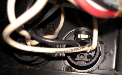
I have realised the pin configuration for the input is non-std, so almost certainly the reason for the issues. I will make up a dedicated cable and see if that fixes it.
Looks like pin 1 (normally ground) is cold. Pin 3 (normally cold) is hot. And pin 2 (normally hot) is Earth! I just used some gender changing plugs to allow connection to my preamp. Unfortunately they are completely sealed, no idea how they are made, but no way to open up to switch around connections, so looks like I will need to make up some dedicated cables.
I will add a photo of input and the output too, where it looks like the speaker connections are on pins 1 and 2.
Last edited:
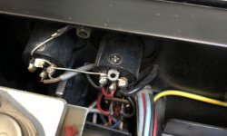
Serious PA amps use 3 & 2 of XLR for a differential inputs to an op amp, so that the common mode voltage (hum) will be rejected and the differential voltage (mike or preamp) cause the music to come out on the speaker. 1 is usually case ground, tied sometimes to a shield on a mike cable and sometimes not.
Crown XLI3500 is using 2 for in+ and 3 for in-.
Crown XLI3500 is using 2 for in+ and 3 for in-.
Amusing I fix the pin out wiring and there is life...I think there will be, as I get nice and low mv dc readings across the speaker outs. I also plan to replace the front panel with a nice 10mm black aluminium plate, which is pre-drilled for an LED indicator.
Any suggestions as to the best/easiest way to wire up a LED to indicate power, from this circuit?
Any suggestions as to the best/easiest way to wire up a LED to indicate power, from this circuit?
Old LED's were designed for 10 ma. I have some new cheap ones ($6 a hundred) that seem to be designed for 20 ma, going by the resistor values shipped with them. People on a recent thread indicated new LED's are designed for 1 ma.
Pick a power supply. 24 v for disconnect relay is best. 2nd best is the rail voltage. worst is the low voltage for the input stage, as that is noise sensitive. Divide that voltage by the current you intend to use. That resistance, or the next higher, is the value you put in series with the LED. Hint, 10 ma is .01 amp. So for a 24 v supply, 24 - 1.2 v is 23 v. 23/.01=2300 ohm or round up, 2400 is next commercial value resistor. Wattage is 2300*.0001 or .23 watt, round up to 1 watt for long life. Resistors run at their rated wattage these days run really hot, hot enough to burn paper PCB's.
If instead of a LED, you have a lamp with a housing and an internal resistor, you'll have to experiment with the current scale of the DVM to determine what external resistor to use with a supply voltage you pick to the the current you think is appropriate.
Last edited:
Some of those high brightness LEDs will put your eye out at 20 mA. Obnoxious blue and green ones that will cast shadows in darkened rooms. That’s why you may only need 1 mA.
If those “miswired” XLR inputs were driven by a balanced source, where the cold side (as well as the hot side) delivered signal, no one would have ever known the difference unless they noticed that the speakers running off of it were out off phase with everything else. Maybe somebody did it intentionally for a phase reversal, although it’s easer just to swap the speaker wires.
If those “miswired” XLR inputs were driven by a balanced source, where the cold side (as well as the hot side) delivered signal, no one would have ever known the difference unless they noticed that the speakers running off of it were out off phase with everything else. Maybe somebody did it intentionally for a phase reversal, although it’s easer just to swap the speaker wires.
Agreed, problem is I am driving from a single ended a pre with xlr output. So only hot has a signal. Pretty sure that explains why I got no sound to the speakers. Will have a new set of xlr cables that I will re-wire tomorrow. Will report back.
Parts-express wasn't selling high brightness LEDs last year. Those LED's are quite tolerable @ 10 ma, used 3 colors of them on an organ shade driver board. Newark didn't sell single color LED's for a couple of years. Just red/green ones. Had to go to nebraskasurplus to get red ones for amp driver biasing.Some of those high brightness LEDs will put your eye out at 20 mA. Obnoxious blue and green ones that will cast shadows in darkened rooms. That’s why you may only need 1 mA.
PA Amps
Some of those amplifiers were for speakers with a transformer, there was a high voltage output from the amplifier and the transformers in each speaker drove the actual speakers.
Just check if it was intended as a PA system amplifier.
Some of those amplifiers were for speakers with a transformer, there was a high voltage output from the amplifier and the transformers in each speaker drove the actual speakers.
Just check if it was intended as a PA system amplifier.
Last edited:
Increase the resistors for the LEDs so that you get barely enough voltage for them to glow.
Another benefit is longer life.
Another benefit is longer life.
Another benefit is longer life.
With a lot of high brightness LEDs their life is actually shortened by running at decreased current
Instead of 2k4 try 3k3 or 3k9 resistors
Life will come to 30k hours from 100k hours.
Or find New Old Stock from HP or others that stopped making them years ago, these will still be 10 mA.
Life will come to 30k hours from 100k hours.
Or find New Old Stock from HP or others that stopped making them years ago, these will still be 10 mA.
decided to replace the input sockets to female XLR and fix the non-std connections/pin arrangement. Slightly bigger job than I had hoped, as I have to drill out the rivets holding old sockets and enlarge the holes for the new sockets. 2 done, 2 to go. Amp may still need other remediation, but will test more thoroughly when I have it hooked up to a signal and attached to cheap speaker. then the bigger job of cap replacement. The actual removal and fitting is the easy bit, disassembly to gain full access and re-assembly is where the time will go
- Home
- Amplifiers
- Solid State
- what would you do with this beast? calling power amp experts