I think I see what the stepped mode is - it "disconnects" the S2 on the top row with the S2 on the second row - but I don't see how this applies in this case? The only "step" is at the terminus opening, and there is no way to have an S6?
Understood - I don't think this design has those, though. Maybe, I'm wrong, but the transition at S2 to S3 has space; and the same for the transition from S3 to S4. The proportion of the step from S4 to S5 vs the length of L45 means it is effectively a gentle taper.
Does it meet this criteria [middle example]? If not, then 'stepped' is technically a better sim: Horn Folding - a brief study of the centerline vs advanced centerline method | AVS Forum
GM
GM
The CAD program lets me drawing polylines that include curves - and then measure the total length. So the segmented corners are the best way to do it by hand, and I think the design has smooth transitions.
FWIW, I have an Excel workbook that makes it easier to design MLTLs with this type of fold (or very similar to this type - I opted for a "vent" with constant CSA rather than one that varies). See the BOXPLAN-MLTL3 option at The Subwoofer DIY Page - Horn Folding
Does it meet this criteria [middle example]? If not, then 'stepped' is technically a better sim: Horn Folding - a brief study of the centerline vs advanced centerline method | AVS Forum
GM
GM
I followed the link but it wasn't clear what "criteria" and "middle example" referred to. Can you clarify? It was a kind of long link....
Thanks
Eric
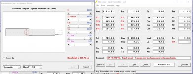
If you're asking me - what is the "stepped function"? Do you mean show the schematic? If so, here it is.
Neil,
I think what BP1 is getting at is that your sim schematic shows a long taper from 445 to 335, when in reality your design tapers pretty abruptly at the fold from 445 to 335, then stays 335 for most of the 90 cm section.
So ideally I think your model should consist of a five sections: straight, taper, straight, taper, straight. But (as far as I know) HR allows only four sections. So I think that means you may be forced to model one of the two "tapers" as a step instead. I'd be inclined to use the taper between the two long sections and the step just before the port.
I'm really just learning HR myself here, and never knew about the "step" option until readings BP1's post. So, there could be better ways, or I could even be totally wrong.
Eric
The CAD program
OK, it's my understanding that CAD + measured HR design builds arrived at the most accurate way to derive a measurement, so presume your way is at least as good.
GM
Can you clarify?
Hmm, it's in the second post, though thought I'd posted its link rather than the original: Horn Folding - a brief study of the centerline vs advanced centerline method | AVS Forum
Guess I should have just posted the image link: https://www.avsforum.com/media/no-title.155199/full
GM
Neil,
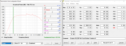
So I'm thinking the the schematic and input page corresponding to your latest drawing should look more like the figure attached. I used the step feature BP1 mentioned, and put the abrupt step at the port.
Note, you can certainly argue about the exact segment lengths that I chose. I don't pretend to know how best to represent the unfolded lengths. Use your best judgment there. I'm just showing the general idea of using the step option.
Two questions:
Why did you choose to have the little 1/2" overhang at the face of the port? I doubt it makes much difference but adds a little more ambiguity as to how exactly to model the port cross section. Is that an aesthetic choice, or for ease of building, or other?
Your driver parameters for Bl, Cms, Rms, and Mmd show up a little different from mine. I just used the DA spec page for inputs. Did you make TS measurements and that's what accounts for the difference? Like the above, I doubt the differences are significant, but I'm just curious about why your numbers are what they are.
Eric
Attachments
Hmm, it's in the second post, though thought I'd posted its link rather than the original:
Thanks GM
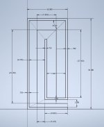
I'm sure you folks know how this goes - a lot of iterations, and a lot of mooshing and squooshing and stretching (in CAD for me), and I am pretty sure I have settled with this design. It lacks the ~2dB dip from ~100Hz-200Hz, and is relatively flat down to ~40Hz; for the 8 ohm Dayton Audio RS225P woofer in particular. But the 4 ohm is only about 2-2.5dB at 40Hz and it is more efficient, so it will blend better with the taller Linaeum tweeter.
The 8 ohm should be an amazing combination with the Radio Shack made Linaeum tweeter, And it probably would also work with the tall one, as well - that is the woofer I have in the stock LT1000 cabinets, which sound incredible, even though there are significant dips in the midbass.
The hardest part about using Hornresp is interpreting the folds and even hairier at the woofer. Because the magnet and the frame are a not insubstantial obstruction. I measured its location in the TL and the path length on the outside as close to the acoustic center as I could estimate. The center of the terminus is simple, though.
I am able to draw a polyline for each segment, that can be measured with a click, that can include curves as part of the polyline.
As I read various descriptions of this, if the mouth of a section is smaller than the rest of the section - the air simply behaves as if the taper was over the whole section. This is essentially the same mechanics that let us have a 90 degree turn without a chamfer surface that makes it look smoother. Air flows where it can, and still pockets form where the air cannot flow.
The driver is the thing moving the air (obviously) and so the distance to the closed end, and the rest of the path toward the open end - hinge around the acoustic center; essentially the voice coil, is how I considered it. The column of air in the closed end resonates based on the distance from the voice coil to the center of the end of the chamber. It is essentially a spring. The air toward the open end actually flows in both directions.
I want to mention the two reasons why I have the chamfered top back corner on the cabinet: to reduce the size of the top surface, which is where the dipole tweeter will be mounted. There will probably need to be a felt pad there, like on the Linaeum Model 10 speaker. The second reason is to reduce the higher frequencies on the inside of the cabinet from reflecting off the back of the cabinet, and coming back out through the cone. It is only paper, after all.
Attachments
Last edited:
Neil,
I like your design and expect it'll sound great but I don't understand why
1) your S1 and S2 are not both 411?
2) your second long segment isn't 343 at both ends?
Eric
I like your design and expect it'll sound great but I don't understand why
1) your S1 and S2 are not both 411?
2) your second long segment isn't 343 at both ends?
Eric
Hi Eric,
I appreciate your question, as that is at the core of how I was attempting to figure out about translating the Hornresp model into a buildable cabinet.
The crux is how I think things will work in area right at the woofer. The main assumption that must be met is the L12 must be to the (acoustic?) center of the woofer to the center of S1.
On my drawing, the diagonal dimension that goes from the top of the vertical baffle through the (acoustic) center of the woofer - is approximately the dividing line between the air that is in the resonant column in the L12 portion, and the air that will be "flowing" in and out along the open ended portion of the enclosure. So that dimension (or a bit less, actually - because of the unknown effect of the space taken up by the woofer magnet and frame, etc) is what I used for S2.
And since that semi-open area will be "flowing" in and out down along L23, I included the 'J' shape as L23. The vertical dimension and the other diagonal dimension from the top of the vertical baffle and the chamfer panel show the narrowing that is happening at the curved part of the 'J'.
In your earlier posts, you had resolved a better solution at the S3 to S4 transition, and I used that method there. I think the S3 section will occur right at the point where the vertical baffle ends, at the corner of where S4 is.
In earlier iterations, I was using then, a small taper in the L45 section, but with the other adjustments, it worked better to keep that segment straight.
So, I hope this is clear, about how I am approaching this? The woofer is where the dividing line is between air that is compressing / resonating in the closed end - and the air that is being pushed and pulled to and from the open end.
The thing we are trying to do with this - is to get as close to the schematic shape and volume as we can, right?
Last edited:
Hi Eric,
I appreciate your question, as that is at the core of how I was attempting to figure out about translating the Hornresp model into a buildable cabinet...
The thing we are trying to do with this - is to get as close to the schematic shape and volume as we can, right?
Neil,
I was afraid you might be getting tired of my questions and comments. But I see we are both trying to figure out how to best represent your design in HR. It's been a great learning experience for me, because I've only made and modeled straight TLs before. I didn't realize how until now that figuring out exactly what dimensions to use in HR to simulate a given folded design would be as challenging/ambiguous as it is.
After your explanation, I'm still confused about where you are getting some of your cross sectional areas. In particular, the 493 for S2 suggests a 9 inch section width, which I don't know where that comes from. So I suspect we are thinking of things a bit differently.
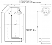
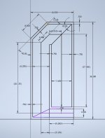
The attached figure should help you understand how I would be inclined to represent your design in HR, using the "centerline" method.
For the present, let's forget about the driver location and just look at the TL segments. Also, I'll use the dimensions in inches instead of cm or cm2.
Per the drawing, I see a TL that has five segments, as follows:
1. Straight (non tapered) 7.5" wide from start to finish, and 27 inches long
2. Tapered section converging from 7.5" to 6.25", 7.625" long.
3. Straight 6.25" wide from start to finish, 29.25" long
4. Tapered section converging from 6.25" to 3", 3.125" long
5. Straight section 3" wide from start to finish, 9" long.
I'll stop here for now, but acknowledge that we still have two challenges to deal with. First, we already have 5 segments, and HR only allows 4. Second we have not positioned the driver.
But let's leave it there for now and let me ask to you Neil, and to other's who have done folded TLs in HR if this seems like a correct application of the "centerline" method?
Thanks,
Eric
Attachments
Hi Eric,
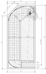
The 493cm2 number comes from the roughly 9" dimension from the top of the vertical baffle that passes through the woofer (at about where the voice coil is) to the surface of the front panel. Since it is the woofer that is driving the air, by definition if has to be along the path that is resonating and moving.
The air in the closed end of the TL can't go anywhere, and the air closer to the open end can be moved. It is is this dividing line that I am estimating falls about on the ~9" dimension that I am calling S2. Since this is the way that Hornresp calculates things - the location of the driver is critical.
The behavior of the air between the driver and the closed end is different from the air in the rest of the TL.
Your drawing has 4 lengths, that are roughly equivalent to how I worked my model. The diagonals are too long to use as the sections, because the air flow "ignores" the corners. The air there essentially stays put - this is why adding the angled corner gussets doesn't help or hinder the performance.
So, if you were to draw and arc that is about tangent to the face of the panels around the corners, and took the radius of those as your section dimension, then that is a fairly accurate area. The centerline of that space (ignoring the dead space in the corners) would be an arc that is more or less what I have drawn.
I hatched in the four volumes that I am using to define the acoustic space inside the enclosure. I drew in the approximate location of the voice coil. Since the motion is emanating from there, the dimensions from there to the boundaries are what Hornresp is working with.
Attachments
Hi Eric,
The 493cm2 number comes from the roughly 9" dimension from the top of the vertical baffle that passes through the woofer (at about where the voice coil is) to the surface of the front panel.
Neil,
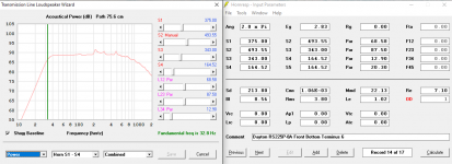
I believe that by using this "diagonal" dimension as the cross-sectional area for S2, you have created volume in the model that simply isn't there in reality. Using your inputs, HR calculates a "System Volume" of nearly 74 liters. But if I calculate the volume of your actual enclosure, I only get around 65 liters, and that even includes the dead air in the corners.
But if I use the step function, and set S2 in segment 1 to 411 (i.e. 7.5"), and set S2S in segment 2 to 343 (i.e. 6.25"), and use all your segment lengths, then the HR System volume comes out at 64.8 liters, which is much more consistent with your actual enclosure volume.
Eric
- Home
- Loudspeakers
- Full Range
- An Improved Transmission Line Alignment