I'm working on my 1st PA subwoofer project which is based on Void Stasys X-Air design.
The plan is to use two B&C 18SW115 woofers instead of the original Void drivers.
Subwoofer design overview

What I'm currently concerned the most about is:
- Circular ports length / rear chamber tuning frequency
- Maximum allowed cone excursion
- LP and HP filters setting
All of these settings depend on each other in some way.
As I don't know how to model this acoustic system as a whole (maybe possible in akabak) I used Hornresp and WinISD to model the subparts of the subwoofer.
Advices/comments/corrections/upgrades of my analysis are more than welcome! 🙂
General setup
Drivers: 2 parallel
Rear chamber volume: 197 Liters
Filters:
LP, Butterworth, n=4, cutoff=140Hz
HP, Butterworth, n=4, cutoff=40Hz
System input power: 6.8kW (134.2V each driver)
WinISD settings


Subpart 1 - circular ports - WinISD
There are four D=101mm circular ports going from the rear chamber.
I modelled the port length and rear chamber tuning frequency in WinISD.
Circular ports

Setup
Tuning freq: 35Hz
Ports: 4x circular L=31.7cm D=10.1cm
WinISD results - transfer function magnitude, SPL, cone excursion


The plan is to use two B&C 18SW115 woofers instead of the original Void drivers.
Subwoofer design overview
What I'm currently concerned the most about is:
- Circular ports length / rear chamber tuning frequency
- Maximum allowed cone excursion
- LP and HP filters setting
All of these settings depend on each other in some way.
As I don't know how to model this acoustic system as a whole (maybe possible in akabak) I used Hornresp and WinISD to model the subparts of the subwoofer.
Advices/comments/corrections/upgrades of my analysis are more than welcome! 🙂
General setup
Drivers: 2 parallel
Rear chamber volume: 197 Liters
Filters:
LP, Butterworth, n=4, cutoff=140Hz
HP, Butterworth, n=4, cutoff=40Hz
System input power: 6.8kW (134.2V each driver)
WinISD settings
Subpart 1 - circular ports - WinISD
There are four D=101mm circular ports going from the rear chamber.
I modelled the port length and rear chamber tuning frequency in WinISD.
Circular ports
Setup
Tuning freq: 35Hz
Ports: 4x circular L=31.7cm D=10.1cm
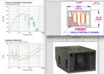
WinISD results - transfer function magnitude, SPL, cone excursion
Last edited:
Subpart 2 - square ports - WinISD
Additionally there are six fixed length square ports. Horn coupling at the square port output is neglected for simplification.
Square ports

Setup
Tuning freq: 63.9Hz (can't go lower, length mods not possible)
Ports: 6x square L=15.2cm, 16.4cm x 6.5cm
WinISD results - transfer function magnitude, SPL, cone excursion


All ports transfer function magnitude and SPL


Additionally there are six fixed length square ports. Horn coupling at the square port output is neglected for simplification.
Square ports
Setup
Tuning freq: 63.9Hz (can't go lower, length mods not possible)
Ports: 6x square L=15.2cm, 16.4cm x 6.5cm
WinISD results - transfer function magnitude, SPL, cone excursion
All ports transfer function magnitude and SPL
Subpart 3 - front compression chamber and horn - hornresp
This subpart is modelled as a single driver with throat adaptor and 3 segment horn.
Currently only 1 driver is used in simulation.

Hornresp setup and results


Questions
1. Is this proper setup for safe cone excursion?
2. Should I model the acoustic system with driver nominal power handling (1.7kW) or continuous power handling (3.4kW)?
3. Is possible to model multiport cabinets in Hornresp?
4. If I'd add a second driver to the current Hornresp setup. Should I just double all S and L values?
This subpart is modelled as a single driver with throat adaptor and 3 segment horn.
Currently only 1 driver is used in simulation.
Hornresp setup and results
Questions
1. Is this proper setup for safe cone excursion?
2. Should I model the acoustic system with driver nominal power handling (1.7kW) or continuous power handling (3.4kW)?
3. Is possible to model multiport cabinets in Hornresp?
4. If I'd add a second driver to the current Hornresp setup. Should I just double all S and L values?
Just a quick FWIW that WinISD cannot simulate this cabinet as-drawn, and I'm not certain that Hornresp can, either. Probably an Akabak job.
The short rectangular ports joining the rear chamber to the short horn would appear to "short out" the long circular ports, but I'd have to run the sims to make sure.
Chris
The short rectangular ports joining the rear chamber to the short horn would appear to "short out" the long circular ports, but I'd have to run the sims to make sure.
Chris
Maple,Additionally there are six fixed length square ports. Horn coupling at the square port output is neglected for simplification.
1. Is this proper setup for safe cone excursion?
2. Should I model the acoustic system with driver nominal power handling (1.7kW) or continuous power handling (3.4kW)?
3. Is possible to model multiport cabinets in Hornresp?
4. If I'd add a second driver to the current Hornresp setup. Should I just double all S and L values?
The circular ports and "horn loaded" ports sum to a single Fb, probably around 40 Hz, considering Void suggests a 38 Hz Hi Pass 24 dB/octave crossover point.
It would be interesting to see an actual measurement of the cabinet's frequency response, 30 Hz - 180 Hz ±3 dB seems unlikely, and would be impossible with a 38 Hz HP.
1) The BC18SW115 has an Xvar of 16mm, which would be a "safe" excursion, and usable in simulation.
It's Xlim is 30mm, 60 mm peak-to-peak excursion before damage.
2) Each BC18SW115 will withstand peaks of 6800 watts, but long term power handling in a cabinet of this sort should probably be limited to around half the AES rating of 1700 watts.
3) As far as I know, other than using an aggregate sum of port length and area, no. This design also has the interesting feature of two different port offset distance in relation to the horn mouth.
4) Your Hornresp sim would be more valid using two offset drivers with a ported rear chamber. The cross-sectional areas of both sides of the throat chamber and horn at various points of the horn path should be combined.
The horn throat dimension is ambiguous due to it's proximity to the horn loaded ports.
Art
Last edited:
weltersys,
Do you have an idea what the Lpt parameter should be set to? Average length of all ports? All ports length sum? The longest/shortest port length?4) Your Hornresp sim would be more valid using two offset drivers with a ported rear chamber. The cross-sectional areas of both sides of the throat chamber and horn at various points of the horn path should be combined.
One back path to output + one reentrant back path + one horn loaded front path :
"Another one for AkAbak, it would seem" (akabak 2.1)
"Another one for AkAbak, it would seem" (akabak 2.1)
Although you can determine the back chamber volume fairly easily from dimensions, it is impossible to "average" the length or area of ports that are so different in cross sectional area and shape .Do you have an idea what the Lpt parameter should be set to? Average length of all ports? All ports length sum? The longest/shortest port length?
I'd suggest using a Lpt that results in an Fb (Frequency of Box tuning) around 40 Hz, based on Void's suggestion of a 38 Hz Hi Pass 24 dB/octave crossover point, though you could vary the Fb down to 28Hz to compare response.
The impedance and excursion minima will be at the Fb.
Void Stasys X-Air design shares functional similarities to the dual 18" EAW SB1000zR cabinet. The considerably smaller SB1000zR uses a pair of round ports in addition to a single large rectangular port between the two drivers at the center of the short "V" horn baffles. The combination of the two different port types ends up with a Fb around 32Hz, as can be seen in the Impedance Magnitude minima at that frequency.
Without seeing an impedance measurement of the Void Stasys X-Air, it will be impossible to determine the accuracy of a Hornresp or Akabak simulation.
Art
Attachments
I chose Lpt=50cm which gave me Fb=40.1Hz. Can't go lower because I don't want longer circular ports.
This is what I got without any filters


I also tried to model the sub with 250L rear chamber which slightly flattened the response and "moved" the peak at 49.6Hz@145.8dB to 44.9Hz@143.4dB.

Maybe some sort of rear chamber lining could improve the response. I know this sim is far from perfect so I will try to sim it in Akabak. Prototype of the sub with adjustable circular ports will be complete soon so I will post some measurements later.
This is what I got without any filters
I also tried to model the sub with 250L rear chamber which slightly flattened the response and "moved" the peak at 49.6Hz@145.8dB to 44.9Hz@143.4dB.
Maybe some sort of rear chamber lining could improve the response. I know this sim is far from perfect so I will try to sim it in Akabak. Prototype of the sub with adjustable circular ports will be complete soon so I will post some measurements later.
Maple,I chose Lpt=50cm which gave me Fb=40.1Hz. Can't go lower because I don't want longer circular ports.
The "horn loaded" ports are ignored in your model, and they are a lot longer than the circular ports in the Void Stasys X-Air design.
Simulating over Xmax/Xvar (16mm) won't translate to reality, as a power increase past Xvar won't linearly increase excursion.
The user guide for the x-air has an impedance plot in it:
https://voidacoustics.com/support/stasys-xair/Stasys_Xair_User_Guide_V1.0.pdf
6th order with fundamental tuning of ~30Hz. Have you considered the IPAL or DS drivers? they may have more output potential.
AKABAK3 can also simulate this kind of box in the lumped acoustic element simulator as well as finite element simulations.
Attachments
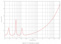
The user guide for the x-air has an impedance plot in it:
https://voidacoustics.com/support/stasys-xair/Stasys_Xair_User_Guide_V1.0.pdf
6th order with fundamental tuning of ~30Hz. Have you considered the IPAL or DS drivers? they may have more output potential.
AKABAK3 can also simulate this kind of box in the lumped acoustic element simulator as well as finite element simulations.
I'd love to simulate the cabinet with every single 18"
 but first of all I need to learn akabak. Regarding the IPAL driver - I see that it's available only in 2ohm version. I'll try to simulate the cab with DS driver which is available in 4ohms.
The IPAL driver aims to maximize motor force (BL^2/Re) which involves packing as much wire (and as little insulator) as possible into the gap and so low voice coil resistance. Its expensive though and especially considering the amplifiers needed to fully power it (EG this two driver box you would run something like a bridged K20 into the two drivers connected in series).
There are some simulation comparisons for some 21" drivers with the IPAL showing a few dB advantage in the SKHORN subwoofer here:
Ricci's Skhorn Subwoofer & Files - Page 25 - Bass Projects - Data-Bass Forums
There are some simulation comparisons for some 21" drivers with the IPAL showing a few dB advantage in the SKHORN subwoofer here:
Ricci's Skhorn Subwoofer & Files - Page 25 - Bass Projects - Data-Bass Forums
Just a quick FWIW that while a K20 will produce signal bridged into a 2ohm load, it won't thank you for it.
I'd be hanging 2x IPAL drivers per channel on an X4L.
Chris
I'd be hanging 2x IPAL drivers per channel on an X4L.
Chris
If im not mistaken(im Always mistaken) you might find that using segments is two fold and recognized in Horn response? If expanding outward in lengths of harmonic intervals, we can place folded segments upon filtering dimensions ideal as standing waves(hw) and propagating fundamentals as (qw) .
Example as a large simple version:
80 cm offset driver to 160 cm there until exit. no void at the overlap from radiator to vent, is concentric...
240, endfired, then 80 compound horn, result is increasingly interesting if thats 120 folded then 120, with 80 off the other side or even 40 folded to 40, and so on.
Because in those steps you can bump CSA, and if tou find the sweet spot you filter at a harmonic step so it keeps evolving as a filter to a goal that we can clearly see in the compounded way as described, and in the offset way as well.
If i combine offset and compounded into an offset and compounded i can find a ‘translex’ or a bass reflex with a bulk of waveguide after. Or a ratio of mass loading a chamber to then open in a game of acoustic inductive and acoustic capacitive elements that i cant describe very well, im just a newbie speaker geek with a curiosity fueled from areas i used to be ‘smart’ in, so i keep bumping into ideas that make me wish i was also and electrical ‘smart’ guy in hide sight as well.....
nevertheless, why is 2/3 and 1/3 so significant if run through 1.404 or .707?
Or something similar to this? i can totally use these to a result and dump it into ‘higher order’ versions too??
this not only in the speakers, but my electrical starts screaming at me and wont allow an upgrade in the same exact ratio as my cabinets fold?
Im Technically off by a bit here, so please bare with me and those ‘fractions of maths’. I sim, i use certain CSAs to promote a certain driver to try and get certain results, bad or good, i unfortunately listen and judge harsh facts as ‘response’ sounding ‘bad or good and quickly have missed so much learning jumping to the next and confusing myself with such a poor gage of technical merit. (My own ears in lots of types of music).
But i clearly have a similar ‘fix’ in addition to the better amplifier and power source? If im Climbing a ladder of compromise vs ??! Uncharted territory we all seek, im just late to the party and trying to catch up using an uninformed mind...
but steps outward and standing waves as propagating intervals to an expanded shape overall(pipe segments in increasing csa) is the golden goose of harmonic USE or ABUSE?
There is another way. endfire a qw pipe from the open end. and tune it to the same as a bass reflex used from the opposite side of the cone. sim as fully offset driver and Vrc/Ap. the fine tiuning of some damping results in another ratio and results are phase oriented again... size that to NOT just be a TL on a higher TL... that was my first and 4th mistakes. an RBI walk with bases loaded is my accidental bump into that one..
Last edited:
The frequency response matches the Stasis X-air published specs, though the 38Hz 24dB crossover in the specs still makes no sense with a 30 Hz low corner.On the speakerplans forum you can find plots of Stasys X. However i am not sure which version.
Attachments
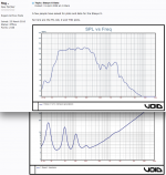
@Art, To me the most logical explanation would be to protect the drivers for over excursion. We do not know what drivers are in the void and what specs they have.
- Home
- Loudspeakers
- Subwoofers
- 2x B&C 18SW115 dual horn subwoofer