Hello everyone,
I'm looking for advice on most accurately modelling a 6th order enclosure. Currently I have a 6th order using two Alpine Type-R 12's but for the next season I've decided to go bigger and have chosen to employ two 18's and fitting them has introduced some unique geometrical constraints that I am not sure how to best approximate in Hornresp.
At a high level the object will be to play broadband 35Hz-100Hz at power levels ~1000W-3000W. I've decided to go with PA drivers this time because B&C 18SW115s came up at a steal of a price (~400CAD each, new). Additionally, they seem to best the the Type-Rs in all other categories; weight, power handling/compression, mid-band sensitivity, still have generous excursion capability.
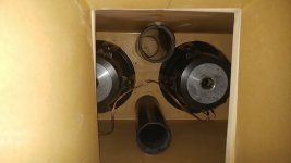
As I've modelled and built 6th's well in the past I was hoping to model conventionally with the rear section firing forward (thus eliminating a mid chamber). Unfortunately after building the rear section it appears that am short 1" in terms of clearance to close the trunk, thus I have to lay the rear section flat and have the drivers firing downward which introduces some interesting considerations of having a mid-chamber (I guess turning this enclosure into technically an 8th order).
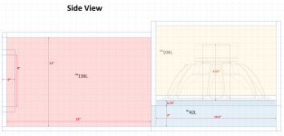
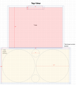
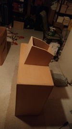
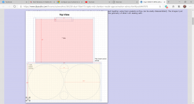
In nutshell, this system comprises of three sections in order to fit inside the trunk (will be sealed together using foam gaskets so they can be easily disassembled). The images I put together PPT below show the general configuration. The side-view I think most clearly shows the geometry of what I am dealing with.


(All values below are net after displacements, wood thickness is 0.75" MDF)
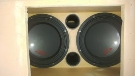
- Rear (yellow): ~104L: houses two B&C 18SW115s, two 22cm 4"ID PVCs, when considered standalone tunes to ~38Hz. The drivers are recessed in this chamber by 0.75" for speaker protection.
- Mid (blue): ~42L: a chamber with an open-top that serves a "pedestal" for which the rear chamber to fire into. In essence, the foot-print of this chamber is identical of the rear chamber that is mounted atop of it. The front of this chamber has an opening to where it mates to the front chamber; the opening here will be ~3"x29.5". This chamber is the crux of the problem as it has an effective axial area of ~895cm^2 (3.75"x37") over a length of 47cm which then steps into to front chamber having an aperture of 571cm^2 (3"*29.5").
- Front (red): ~136L: this chamber sleeves the inside portion of the trunk and mates up to the ski pass (~489cm^2 of port, ~2" in length but this can be adjusted as needed). From the top, the front chamber is slightly narrower than the rear/mid chambers.
Modeling is done in Hornresp, with 1kW of power, using semi-inductance parameters I've derived from the impedance curve. The volume of each section is quite trivial (~286L total in each model) but it seems that the geometry (in terms of length/areas) results in significant deviations from model to model. I would appreciate any advice on what would be most appropriate. The problem at hand is that I don't think I can bin the mid and front chambers and consider them simply in terms of volume as I think there are some compression effects happening in the mid-chamber.
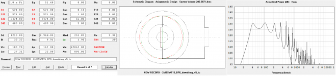
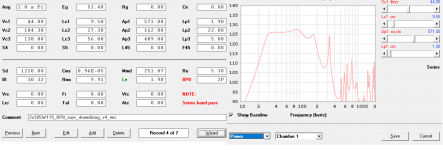
Model 1: TH1 using a standard rear chamber, mid-chamber is approximated ~895cm^2 using two horn sections (this not account for the step change into a 29.5"*3" (571cm^2) aperture into the front chamber.

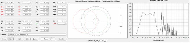
Model 2.1: TH1 using a standard rear chamber, mid-chamber is accounted for in Vtc/Atc; Atc is 4416cm^2 giving a length of 9.52cm, this loads into the front chamber through the 29.5"*3" aperture into the front chamber which is accounted for here

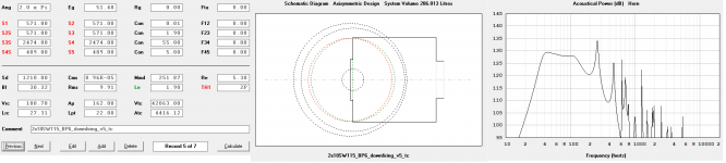
Model 2.2: TH1 using a standard rear chamber, mid-chamber is accounted for in Vtc/Atc; Atc is 895cm^2 giving a length of 47cm, this loads into the front chamber through the 29.5"*3" aperture into the front chamber which is accounted for here

There are a couple critical questions in regards to the models:
- Models 2.1 and 2.2 are quite similar with the difference being the consideration of the "length" of the chamber relative to everything else. Is it seen as 9.52cm (height) or 47cm long (length). I like these in that they both consider loading into the front chamber through the step change in the mid chamber but are quite different due to the considered length of the mid-chamber? What is most appropriate? Or maybe something in the middle, like a 24cm approximation of length.
- What is the most "correct" placement of the front and rear entry points? Effectively, I would like to have woofers and port as a single point loading in at 25cm (the center point of mid-chamber) but I don't think that it's possible to do with more segments, which I don't believe Hornresp supports. Given horn-resps constrains it seems that the driver and vents are offset by some distance which results in model differences between the two.
Model 3: BP8 Wizard where the mid-chamber step is considered as a 0.75" port of area 571cm^2. I think this one is the most ambiguous of what is happening in terms of geometry.

All in all, I think the responses in all models looks fairly workable in the frequency band I want to target but it would be nice to have a relatively flat response with slight emphasis at 40Hz (which model 2.1 presents).
As always, I would be very greatful for any advice and insights on this design.
I'm looking for advice on most accurately modelling a 6th order enclosure. Currently I have a 6th order using two Alpine Type-R 12's but for the next season I've decided to go bigger and have chosen to employ two 18's and fitting them has introduced some unique geometrical constraints that I am not sure how to best approximate in Hornresp.
At a high level the object will be to play broadband 35Hz-100Hz at power levels ~1000W-3000W. I've decided to go with PA drivers this time because B&C 18SW115s came up at a steal of a price (~400CAD each, new). Additionally, they seem to best the the Type-Rs in all other categories; weight, power handling/compression, mid-band sensitivity, still have generous excursion capability.
As I've modelled and built 6th's well in the past I was hoping to model conventionally with the rear section firing forward (thus eliminating a mid chamber). Unfortunately after building the rear section it appears that am short 1" in terms of clearance to close the trunk, thus I have to lay the rear section flat and have the drivers firing downward which introduces some interesting considerations of having a mid-chamber (I guess turning this enclosure into technically an 8th order).
In nutshell, this system comprises of three sections in order to fit inside the trunk (will be sealed together using foam gaskets so they can be easily disassembled). The images I put together PPT below show the general configuration. The side-view I think most clearly shows the geometry of what I am dealing with.
(All values below are net after displacements, wood thickness is 0.75" MDF)
- Rear (yellow): ~104L: houses two B&C 18SW115s, two 22cm 4"ID PVCs, when considered standalone tunes to ~38Hz. The drivers are recessed in this chamber by 0.75" for speaker protection.
- Mid (blue): ~42L: a chamber with an open-top that serves a "pedestal" for which the rear chamber to fire into. In essence, the foot-print of this chamber is identical of the rear chamber that is mounted atop of it. The front of this chamber has an opening to where it mates to the front chamber; the opening here will be ~3"x29.5". This chamber is the crux of the problem as it has an effective axial area of ~895cm^2 (3.75"x37") over a length of 47cm which then steps into to front chamber having an aperture of 571cm^2 (3"*29.5").
- Front (red): ~136L: this chamber sleeves the inside portion of the trunk and mates up to the ski pass (~489cm^2 of port, ~2" in length but this can be adjusted as needed). From the top, the front chamber is slightly narrower than the rear/mid chambers.
Modeling is done in Hornresp, with 1kW of power, using semi-inductance parameters I've derived from the impedance curve. The volume of each section is quite trivial (~286L total in each model) but it seems that the geometry (in terms of length/areas) results in significant deviations from model to model. I would appreciate any advice on what would be most appropriate. The problem at hand is that I don't think I can bin the mid and front chambers and consider them simply in terms of volume as I think there are some compression effects happening in the mid-chamber.
Model 1: TH1 using a standard rear chamber, mid-chamber is approximated ~895cm^2 using two horn sections (this not account for the step change into a 29.5"*3" (571cm^2) aperture into the front chamber.
Model 2.1: TH1 using a standard rear chamber, mid-chamber is accounted for in Vtc/Atc; Atc is 4416cm^2 giving a length of 9.52cm, this loads into the front chamber through the 29.5"*3" aperture into the front chamber which is accounted for here
Model 2.2: TH1 using a standard rear chamber, mid-chamber is accounted for in Vtc/Atc; Atc is 895cm^2 giving a length of 47cm, this loads into the front chamber through the 29.5"*3" aperture into the front chamber which is accounted for here
There are a couple critical questions in regards to the models:
- Models 2.1 and 2.2 are quite similar with the difference being the consideration of the "length" of the chamber relative to everything else. Is it seen as 9.52cm (height) or 47cm long (length). I like these in that they both consider loading into the front chamber through the step change in the mid chamber but are quite different due to the considered length of the mid-chamber? What is most appropriate? Or maybe something in the middle, like a 24cm approximation of length.
- What is the most "correct" placement of the front and rear entry points? Effectively, I would like to have woofers and port as a single point loading in at 25cm (the center point of mid-chamber) but I don't think that it's possible to do with more segments, which I don't believe Hornresp supports. Given horn-resps constrains it seems that the driver and vents are offset by some distance which results in model differences between the two.
Model 3: BP8 Wizard where the mid-chamber step is considered as a 0.75" port of area 571cm^2. I think this one is the most ambiguous of what is happening in terms of geometry.
All in all, I think the responses in all models looks fairly workable in the frequency band I want to target but it would be nice to have a relatively flat response with slight emphasis at 40Hz (which model 2.1 presents).
As always, I would be very greatful for any advice and insights on this design.
Attachments
Interesting approach to modelling a series-tuned 6th order BP alignment.
The port area for the rear section looks way small though. The end result could be significant vent compression effects at higher power levels.
The port area for the rear section looks way small though. The end result could be significant vent compression effects at higher power levels.
Hi Brian,
Yes, port area was one of my main concerns when I built my first BP6S enclosure in that vehicle (two SWR-1243Ds, which happen to be my favorite well-rounded sub drivers of all-time).
I don't want to digress too much but for interest's sake that enclosure looked as follows and had predicted port velocities on the output of ~25-40m/s in the 1000-2000W range (this is theoretical of course, as concessions have to be made in terms of real reactive power, power compression, port compression, etc...). In practice though, even at such power levels the output from the skipass had no chuffing and was honestly quite effortless.
Another concern of mine were the interior ports, but that's another story. From practical testing in the car audio community it was found that when they begin to compress the enclosure starts to act closer to a 4th orders. Ultimately though for such enclosures I like to use PVC pipes as you can retroactively adjust them (and even have them sticking out of the box) unlike slot ports.
For interest's sake:


In the case of the B&C 18SW115s it seems that at 1kW level port velocities are acceptable, but you are right, at 3kW it's quite concerning (~40-70m/s). I'm afraid that the amount of port area at the ski-pass is a hard constraint and cannot be changed. That being said, I think even at 1kW of power this setup will be extremely loud and I am building this setup with a lot of headroom in terms of power handling so I don't really expect to play 3kW in a realistic setting. As a side note, at 1kW this setup will not even see significant power compression whereas the Alpines did get notable quieter (at least ~3dB on the ear-o-meter after they had "warmed" up) after extended use. For the sake of curiosity though I'm interested in finding out how much air you can stuff through a skipass... LOL
As for other considerations, the front chamber port will basically be a hole in the baffle (which will be wedge shaped to mate up to the rear seat, not modelled here for the sake of simplicity but the impact of that is nominal). The effective length will be ~2" which is the length of plastic ski-pass frame. From what I've read in literature it seems that extremely short ports that are also quite square in ratio (~1:1) will have even less propensity for noise/compression.
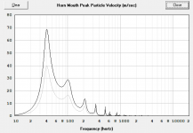
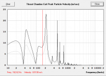
Below are velocities at 1kW (grey) and 3kW (black) at three sections (using model 2.2 for reference). Overall they appear to be acceptable at 1kW (<40m/s) with concerns in the 35-50Hz region (40-70m/s) at 3kW but I'm interested in finding out in practice what really happens at this higher power level.
Mid chamber (throat chamber exit section where the woofer is firing into, which mates to the front chamber):

Front chamber (skipass):

Apart from such high-power non-linearities for practical purposes at ~1kW it should work well.
Ultimately though, I think what's happening in the mid-chamber is going to be x-factor. From a velocity standpoint velocities here are relatively low (~15m/s @ 3kW) so I don't see a bottleneck in this regard. It's clear however that there is a unique resonance happening here and must somehow be modelled as it affects the loading of the internal 4" ports and ultimately what's happening on the ski-pass exit. Based on different modelling approaches it can induce a +/- 3dB ripple in the passband as you've see in the various models which are essentially equivalent in air-space but with varying geometries.
Yes, port area was one of my main concerns when I built my first BP6S enclosure in that vehicle (two SWR-1243Ds, which happen to be my favorite well-rounded sub drivers of all-time).
I don't want to digress too much but for interest's sake that enclosure looked as follows and had predicted port velocities on the output of ~25-40m/s in the 1000-2000W range (this is theoretical of course, as concessions have to be made in terms of real reactive power, power compression, port compression, etc...). In practice though, even at such power levels the output from the skipass had no chuffing and was honestly quite effortless.
Another concern of mine were the interior ports, but that's another story. From practical testing in the car audio community it was found that when they begin to compress the enclosure starts to act closer to a 4th orders. Ultimately though for such enclosures I like to use PVC pipes as you can retroactively adjust them (and even have them sticking out of the box) unlike slot ports.
For interest's sake:
In the case of the B&C 18SW115s it seems that at 1kW level port velocities are acceptable, but you are right, at 3kW it's quite concerning (~40-70m/s). I'm afraid that the amount of port area at the ski-pass is a hard constraint and cannot be changed. That being said, I think even at 1kW of power this setup will be extremely loud and I am building this setup with a lot of headroom in terms of power handling so I don't really expect to play 3kW in a realistic setting. As a side note, at 1kW this setup will not even see significant power compression whereas the Alpines did get notable quieter (at least ~3dB on the ear-o-meter after they had "warmed" up) after extended use. For the sake of curiosity though I'm interested in finding out how much air you can stuff through a skipass... LOL
As for other considerations, the front chamber port will basically be a hole in the baffle (which will be wedge shaped to mate up to the rear seat, not modelled here for the sake of simplicity but the impact of that is nominal). The effective length will be ~2" which is the length of plastic ski-pass frame. From what I've read in literature it seems that extremely short ports that are also quite square in ratio (~1:1) will have even less propensity for noise/compression.
Below are velocities at 1kW (grey) and 3kW (black) at three sections (using model 2.2 for reference). Overall they appear to be acceptable at 1kW (<40m/s) with concerns in the 35-50Hz region (40-70m/s) at 3kW but I'm interested in finding out in practice what really happens at this higher power level.
Mid chamber (throat chamber exit section where the woofer is firing into, which mates to the front chamber):
Front chamber (skipass):
Apart from such high-power non-linearities for practical purposes at ~1kW it should work well.
Ultimately though, I think what's happening in the mid-chamber is going to be x-factor. From a velocity standpoint velocities here are relatively low (~15m/s @ 3kW) so I don't see a bottleneck in this regard. It's clear however that there is a unique resonance happening here and must somehow be modelled as it affects the loading of the internal 4" ports and ultimately what's happening on the ski-pass exit. Based on different modelling approaches it can induce a +/- 3dB ripple in the passband as you've see in the various models which are essentially equivalent in air-space but with varying geometries.
Attachments

Last edited:
Those ports that are just "holes in the baffle" are likely to end up being quite non-linear. How much difference do they actually make to the overall output of your design?
For the 18SW115s alignment, the only port that I considered a hole in the baffle will be the port at the ski-pass. In the initial diagrams, the front port is actually not in the box but just a placeholder. In practice, it's effective physical length will be ~5cm when it is mated up to the "skipass sleeve" which is basically a plastic beauty cover... so basically basically 0.75" hole in the MDF + another 1.5" or so of sleeve. It can obviously be extended as needed.
Making this port longer (say for example ~10cm) drops the the average response by a couple dB, and bumps the low-peak by a couple dBs as expected.
This is what that the response looks like using model 1 using 5cm (grey) vs. 10cm (black) of port at the skipass.

If I consider model 2.2 as closer to the truth, then the following happens respectively at 5 and 10cm.

Whatever the case may be it's clear that it's going to be loud but it's a big puzzle as to what could the correct model could be given the mid-chamber. The good thing about this design is that due to modularity there is a lot of room to make adjustments retroactively, in terms of port, even the box.
Making this port longer (say for example ~10cm) drops the the average response by a couple dB, and bumps the low-peak by a couple dBs as expected.
This is what that the response looks like using model 1 using 5cm (grey) vs. 10cm (black) of port at the skipass.
If I consider model 2.2 as closer to the truth, then the following happens respectively at 5 and 10cm.
Whatever the case may be it's clear that it's going to be loud but it's a big puzzle as to what could the correct model could be given the mid-chamber. The good thing about this design is that due to modularity there is a lot of room to make adjustments retroactively, in terms of port, even the box.
Attachments
Last edited:
Oh ok, I see.
In this particular TH1 configuration (models 1 and 2) Hornresp is not letting me see the port velocities in this section but in the BP8S wizard model (approximating the BP6S) we can get an idea. This model also features the lowest extension as well.
We can see that with the twin 4" PVCs the port velocity at 1kW is acceptable down to 30Hz. It's quite interesting as the other resonances are loading down the inner ports... common sense would dictate that you would get a huge velocity at 40Hz but that does not appear to be the case.

Unlike parallel bandpasses, series bandpasses are weird animals as it's quite clear that all port tunings are not mutually exclusive. They all seem to work in conjunction with one another resulting in interesting tuning shifts at each node.
The rear chamber in the above design, at face value considered as a simple vented box, is 104L tuned to 38Hz and would be considered grossly undersized for two low QTS 18s. However, when placed in a series alignment it seems that conventional logic generally goes out the window. From others' conjecture and testing it seems that people like to use small rear vented sections and small rear ports in series tuned enclosures, and again if they do compress they act somewhere in between a 4th and a 6th BP.
In this particular TH1 configuration (models 1 and 2) Hornresp is not letting me see the port velocities in this section but in the BP8S wizard model (approximating the BP6S) we can get an idea. This model also features the lowest extension as well.
We can see that with the twin 4" PVCs the port velocity at 1kW is acceptable down to 30Hz. It's quite interesting as the other resonances are loading down the inner ports... common sense would dictate that you would get a huge velocity at 40Hz but that does not appear to be the case.
Unlike parallel bandpasses, series bandpasses are weird animals as it's quite clear that all port tunings are not mutually exclusive. They all seem to work in conjunction with one another resulting in interesting tuning shifts at each node.
The rear chamber in the above design, at face value considered as a simple vented box, is 104L tuned to 38Hz and would be considered grossly undersized for two low QTS 18s. However, when placed in a series alignment it seems that conventional logic generally goes out the window. From others' conjecture and testing it seems that people like to use small rear vented sections and small rear ports in series tuned enclosures, and again if they do compress they act somewhere in between a 4th and a 6th BP.
Attachments
The lower Fb of that alignment seems to be more around 26 Hz BTW, considering where the peak in the vent particle velocity is. The location of the lowest points in the impedance curve (or the lowest points in the cone displacement curve) can confirm this.
The lower Fb of BP6S alignment is set by both the front and rear enclosures and the front and rear vents.
With a lower Fb that low however, I'd be tempted to just seal them up to see if there's any significant difference, particularly if this is destined for car audio use, as cabin gain is going to give a nice big boost at low frequencies anyway.
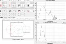
All models are quite similar but for sake of simplicity I'll just show model 2.2.

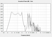
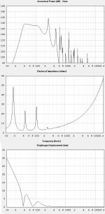
Effectively we are going to have three peaks: at two tunings and one driver fs. I had to do a double take to make sure I took snapshots between the same model but the images indeed are correct. Threw in driver displacement for good measure (1kW by the way)
From what I can tell is that driver fs really goes out the window (32Hz nominally, whereas the first peak is at 18Hz). Also the box doesn't roll off hard until 37Hz whereas the corresponding impedance peak is at 45Hz. Upper impedance peak is at 110Hz.
Attachments
Last edited:
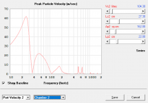
That's curious. I'd have expected the particle velocity of the internal vents to peak at the lower Fb. In your design, the particle velocity is almost at a minimum, if the location of the lower Fb based on the excursion curve is correct.
Here's what the particle velocity for the internal vent of a BP6S that I just designed today looks like. And it's peaking at Fb. Oh, double-clicking on the graph should cause Hornresp to highlight the lower Fb, as indicated in the attached image.
Here's what the particle velocity for the internal vent of a BP6S that I just designed today looks like. And it's peaking at Fb. Oh, double-clicking on the graph should cause Hornresp to highlight the lower Fb, as indicated in the attached image.
Attachments

Last edited:
Didn't know that. That's a good tip for the wizard, should come in helpful in the future.
But yes, I agree that is what I would also expect...
I think this is some sort of a unconventionality that's induced by having this "mid-chamber". In all models it manifests itself in some capacity but I could see something like that happening as the ported drivers have huge area (Sd of ~2400cm^2 + port) firing into a chamber with a relatively short cross sectional area of 900cm^2 with a ~500cm^2 stepped exit before going into the front chamber. The velocity out of this chamber can be up to 7-15m/s (1-3kW respectively) which means that there is some resonance here that is not significant to appear on it's own but given the passband will manifest in the other impedance peaks.
I don't think the wizard for the BP6S fully entails this nuance as it just thinks of the the box as two simple rectangular sections. I don't think the model is fully representative in my case as I would basically bin the front and mid chamber as one, neglecting all geometry. However the BP8S wizard can model this in some pseudo capacity (basically considering the mid-chamber volume as the 3rd chamber with a port length of 0.75").
I think the TH1 models are going to be closest to ground truth despite some shortcomings in regards to entry points but I despite this they seem to take into account the potential geometry most closely (I'm leaning towards the ground truth being somewhere been 2.1 and 2.2)...
Last edited:
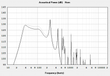
Right - mystery solved. Your model is an 8th order BP, not 6th order. The vent velocity curves for the rear enclosure in an 8th order BP system are a bit different. At least, Hornresp says so 🙂.
The impedance curve will be quite different as well (four main peaks, instead of three). And three excursion minimums in the passband, instead of two.
The impedance curve will be quite different as well (four main peaks, instead of three). And three excursion minimums in the passband, instead of two.
LOL, yeah... I guess whether to consider this a BP6S or BP8S is the crux of the problem... 😉
From a wizard perspective, approximating this as a BP8S (model 3) we can get the four peaks, but can the mid-chamber really be considered "ported" by way of the wizard's nomenclature if it's only 0.75" deep?
On the contrary the non-wizard TH1 profiles are approximating something along the lines of a BP6S but adding some nuance of the 8S element by way of either stepped horn sections or using the Vtc/Atc parameter.
Then again, maybe I'm going crazy and I've been using the TH1 setting to model BP6S enclosures wrong the whole time.... LOL 🙂
Last edited:
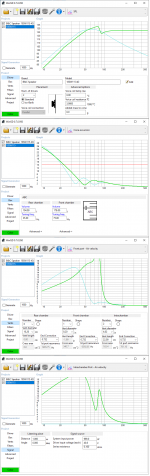
I have no experiences building 6th order (or whatever order), but I have played some with WinISD and I thought what your case would look like in WinISD.
Apart from a 4th or 6th order you can choose 'ABC' which has 2 chambers and 3 ports to configure. In this case the rear chamber has '0' ports, but only 2 intrachamber ports. I put the volume of the blue and red together.
Unfortunately the vent length is of the front chamber is not editable, but I tuned the frequency to match your length.
I don't know what to think of the results, but I put an regular 6th order with same drivers and boxvolumes at the back for comparison.
Dont know if it helps, but success with you sub.
Attachments
Last edited:
Then again, maybe I'm going crazy and I've been using the TH1 setting to model BP6S enclosures wrong the whole time.... LOL 🙂
With a few minor exceptions, modeling the same alignment using different methods in Hornresp tends to produce similar results, particularly at the lower end of the passband. This makes sense - if the "topology" of the model used in each sim is the same, then the results should be the same, or at least one of the sims is incorrect (or, least likely, the Hornresp predictions of the sim's output are incorrect).
However, you also have to take into consideration where the topology of what you're trying to build differs from the Hornresp sim, and the potential impact that might have. Case in point - the recent BP6S workbook that I put together. While it shows that THs are basically sixth order series-tuned bandpass alignments taken to their logical limits, It's also not a perfect model because it doesn't take into effect the small volume located in front of the driver's cone and the impact of the driver's chassis sitting in the front volume. And then there's also the question of what the impact might be of the rear enclosure's "vent" emerging into the front enclosure's side rather than dead center of its rear panel.
In your case, you're using two models of the same layout, that seem to be predicting quite different results. This suggests that at least one of those Hornresp sims of your planned build may not be an accurate enough reflection of its topology. I suggest going back and checking each step to see if one of your assumptions is off.
I have no experiences building 6th order (or whatever order), but I have played some with WinISD and I thought what your case would look like in WinISD.
Apart from a 4th or 6th order you can choose 'ABC' which has 2 chambers and 3 ports to configure. In this case the rear chamber has '0' ports, but only 2 intrachamber ports. I put the volume of the blue and red together.
Unfortunately the vent length is of the front chamber is not editable, but I tuned the frequency to match your length.
I don't know what to think of the results, but I put an regular 6th order with same drivers and boxvolumes at the back for comparison.
Dont know if it helps, but success with you sub.
Thanks for the simulation... I completely forgot that WinISD had the ABC box option. I suppose the must have introduced that feature in the last alpha release which I didn't use very much due to weird crashes that occured when parameters were entered that would trigger a divide by zero.
From the inherent parameters it definitely looks like the 18SW115 can work in a 6th order quite well (cyan curve) however I don't believe the ABC box model takes into account the geometry and configuration of a BP6S alignment.
By setting the rear port in the WinISD to zero it effectively turns the enclosure into a 4th order. I think it's quite clear as the box peaks hard and rolls off (like a 4th order). If this port is set to a non-zero value then by definition on the inherent model the ports are not actually firing into the enclosure but rather firing out of it as WinISD can only do parallel alignments.
That being said though, looking at the total volume and the 6th order parallel model (which I suppose the cyan curve is), it looks like there is enough airspace to do what I need the drivers to do.
With a few minor exceptions, modeling the same alignment using different methods in Hornresp tends to produce similar results, particularly at the lower end of the passband. This makes sense - if the "topology" of the model used in each sim is the same, then the results should be the same, or at least one of the sims is incorrect (or, least likely, the Hornresp predictions of the sim's output are incorrect).
However, you also have to take into consideration where the topology of what you're trying to build differs from the Hornresp sim, and the potential impact that might have. Case in point - the recent BP6S workbook that I put together. While it shows that THs are basically sixth order series-tuned bandpass alignments taken to their logical limits, It's also not a perfect model because it doesn't take into effect the small volume located in front of the driver's cone and the impact of the driver's chassis sitting in the front volume. And then there's also the question of what the impact might be of the rear enclosure's "vent" emerging into the front enclosure's side rather than dead center of its rear panel.
In your case, you're using two models of the same layout, that seem to be predicting quite different results. This suggests that at least one of those Hornresp sims of your planned build may not be an accurate enough reflection of its topology. I suggest going back and checking each step to see if one of your assumptions is off.
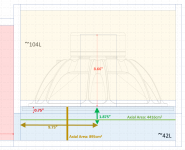
I actually did a little reading in the Hornresp dialogs and it turns out that in the throat chamber the Atc parameter refers to the "average cross-section area normal to the axis". As such, I interpreted the axis as bending in the "mid-chamber"... that is to say that you have the axial area of the driver baffle (4416cm^2 for 4.76cm) and then when it bends the axial area changes to (895cm^2 for 24.5cm).
You can see that in the illustration here:
If were compute the average area over this "bend" then we get an average chamber length of ~30cm with a cross-sectional area of 1335cm^2.
By defining the mid-chamber entirely by this throat chamber approximation we free up the TH1 horn segments to model the entry as the 571cm^2 step as well as the rest of the rear chamber. On top of that, we can place the entry points in the correct locations.
Response looks as follows which is somewhere in between all the prior TH1 models where concessions were made by only placing one of the two entry points in the correct location. Now, the entries are placed "on top" (0.1cm) of one another. Compared to the TH1 model the most deviant model was the BP8 wizard (the one that was picture perfect flat down to 28Hz) but in truth I don't believe that this takes into account the geometry most closely as well as for the fact that the mid-chamber will probably not have a significant enough resonance to make it a true 8th order as the wizard would suggest.
The TH1 model still entails the nuance of this box being a mild 8th order... I think we can still see the manifestation of this 4th resonance in the mid-chamber as a small resonance at ~225Hz (which makes sense as from a chamber of 40 liters with a 0.75" "port" of 571cm^2). Aside from this, in terms of acoustical power, there is an element of compression in this chamber which causes loading of the rear ports as well as giving a slight notch at 40Hz (Atc < 2xSd). Overall, I think it makes a lot of sense.
This what the model looks like:
Attachments

Last edited:
- Home
- Loudspeakers
- Subwoofers
- Dual 18SW115 BP6S with a "mid chamber", model approximation advice?