I am coming up with a large ported home theater subwoofer enclosure design. The goal is a low tune with minimal port noise. But with a port that is large enough to keep port air velocity low, I am now getting a calculated first port resonance of 87Hz in WinISD.
I can of course get it over 100Hz if i make the port slightly undersized or make the internal chamber oversized. But is a 100Hz port resonance still a big problem?
How much do i have to worry about port resonance?
I can of course get it over 100Hz if i make the port slightly undersized or make the internal chamber oversized. But is a 100Hz port resonance still a big problem?
How much do i have to worry about port resonance?
Consider an offset driver TL instead. You can null out that first vent resonance with that type of alignment.
I am sorry, I don't know if i entirely understand. Are you saying that the port resonance will be a big problem with the standard ported design?
In order to answer the question better, it would probably help others to know how and where you're setting your newly proposed subs LPF? If setting at 40Hz with a typical 24dB/Octacte, you'll be asking your sub to produce approx 24dB less at 80Hz so is a 6dB (for example) hump at 87Hz a big deal? If you're putting your LPF at 100Hz, the port resonance will sit in the passband and might be undesirable - how much so, I'm not sure. My 1st resonance was measurable, but I've also seen a sub designed on this site earlier this year with a low first port resonance that didnt show up in the designers measurements.
Here's my subs first port resonance showing up in measurements. I set LPF to 60Hz so not an issue
Project – 2 x Peerless XLS 10” 20Hz tuned slot port subwoofer
Project – 2 x Peerless XLS 10” 20Hz tuned slot port subwoofer
Here's an example where a 100Hz resonance would have been expected in measurements, but was not an issue - posts 43 to 47 -
Home theater subwoofers with UM15-22 drivers and Crown K2 amp
Home theater subwoofers with UM15-22 drivers and Crown K2 amp
What Brian suggested shifts that issue up
By 20-30+hz (next harmonic -void- and smaller and farther from an XO point needed.
By 20-30+hz (next harmonic -void- and smaller and farther from an XO point needed.
Here's an example where a 100Hz resonance would have been expected in measurements, but was not an issue - posts 43 to 47 -
Home theater subwoofers with UM15-22 drivers and Crown K2 amp
The location and amplitude of the resonance modes depends on several things, e.g:
1. The vent dimensions
2. The box dimensions
3. The location of the vent in the box
4. The location of the driver in the box
If the simulation program doesn't take at least those four things into consideration, then it's basically useless as far as predicting the impact of those resonance modes is concerned.
I am not exactly sure what will be the best setting for the LPF to blend with the other speakers yet. But likely between 50Hz-80Hz. And yes, I could do a super sharp roll off in a worst case scenario. But finding out how much these resonances effect things has been hard to find out and i would rather not have the problem if it is big.In order to answer the question better, it would probably help others to know how and where you're setting your newly proposed subs LPF?
Interesting. Though i have no knowledge of this concept. Someone might have to explain it to me.What Brian suggested shifts that issue up
By 20-30+hz (next harmonic -void- and smaller and farther from an XO point needed.
I read through that, And downloaded Hornresp. I may need someone with more expertise with the program to tell me if i am doing something wrong, But using a offset driver only shifted the first bad peak up to 100Hz when calculating a TL with a frequency response almost flat down to 20Hz. And the idea of designing a gigantic snaking port box where the driver neatly sits at the exact distance down the port for it to be correct sounds like my own personal hell.
I think i am in over my head haha
I think i am in over my head haha
That's why I created and use the BOXPLAN workbooks on my site to help with designing the box.
The Subwoofer DIY Page - Horn Folding
The Subwoofer DIY Page - Horn Folding
I read through that, And downloaded Hornresp. I may need someone with more expertise with the program to tell me if i am doing something wrong, But using a offset driver only shifted the first bad peak up to 100Hz when calculating a TL with a frequency response almost flat down to 20Hz. And the idea of designing a gigantic snaking port box where the driver neatly sits at the exact distance down the port for it to be correct sounds like my own personal hell.
I think i am in over my head haha
What driver(TS parameters) ?
Fs: 29.6Hz
RE: 3.80
Qes: 0.400
Qms: 4.650
Qts: 0.370
Vas: 59.90L
MMS: 361.4g
CMS: 0.0800mm/N for WinISD: 8.17E-05 in Hornresp
SD: 711.1cm^2
BL: 25.6NA
LE: 2.53 mH
XMax: 30mm one way
It is a 15" sub with a 11" mounting depth if that also helps for figuring out the size. And up to 2000W RMS might be used on it.
Also, My question is yet to be answered. On how bad the first port resonance will be with a normal ported design. If it manifests as just a peak that can be EQ'd out then it isn't much of a problem. But if it starts ringing at that frequency with delayed notes and perhaps harmonic clashing then it is a real problem. What exactly should i expect? Because if it is just a peak, Then no problem.
Fs: 29.6Hz
RE: 3.80
Qes: 0.400
Qms: 4.650
Qts: 0.370
Vas: 59.90L
MMS: 361.4g
CMS: 0.0800mm/N for WinISD: 8.17E-05 in Hornresp
SD: 711.1cm^2
BL: 25.6NA
LE: 2.53 mH
XMax: 30mm one way
It is a 15" sub with a 11" mounting depth if that also helps for figuring out the size. And up to 2000W RMS might be used on it.
Also, My question is yet to be answered. On how bad the first port resonance will be with a normal ported design. If it manifests as just a peak that can be EQ'd out then it isn't much of a problem. But if it starts ringing at that frequency with delayed notes and perhaps harmonic clashing then it is a real problem. What exactly should i expect? Because if it is just a peak, Then no problem.
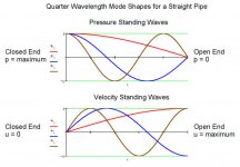
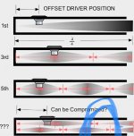
Its a void due to cancelation and has to be dealt with acoustically. the overlap of the out going phase at the vent and the driver ‘direct’ radiator is the result of 90 degrees as the length of only one quarter wave of the actual wave that has 3/4 more left in its cycle. If you draw this on the side of an unfolded TL and create 3 more of the same TLs in succession, the entire waveform ‘S’ or sine becomes apparent. Its a circle. 4 quadrants: 90,180,270 and 360 degrees.
And a pressure wave (shown in the pic as a qw) has Zero pressure zones(null) crossing and lagging behind is Velocity... Extend that and the pressure/no pressure is closed (and open end in folding) end pipe harmonics. instead of a straight TL, 3 folded segments or a driver ~1/3 down the line or both in an alternative length it or design will smother that void in the qw speaker.
. Examples of this as 240cm TL attached to an 80 cm TL from the other side of a driver, or 80 cm folded 3 times
or 80 cm then driver entry then 160cm to exit.
Attachments
Try 400cm2 for 105 cm (offset driver L12) then 100cm in the L23 and L34 segments.
Switch that From ‘Nd’ and ‘OD’ mode in horn and youll see as Nd is not offset (see schematic) .
thats a decent size TL for Vas and the only issue is fitting that 11” deep motor inside or flipping it to motor ‘out’. adding a Vtc/Atc as a brief entry point sized for the big motor depth is the same as making that driver entry at the ‘fold’. basically you can create room form that magnet and adjust the line to compensate any details youll see in the response shape change(the void can be filled and the extended bandwidth to the next is likely well beyond the xo point youll find usefull to ‘mains’ or mids.
But if you start with 350-400cm2 at 270-300cm, its easier/funner to learn(explore) from a size thats friendly for TS parameters...
CMS: 8.17E-05 in Hornresp
Just to clarify, if Sd = 711.10 cm^2 and Vas = 59.90 litres, then Cms = 8.31E-05 m/N in Hornresp.
- Home
- Loudspeakers
- Subwoofers
- First Port Resonance Too Low?