Our audio shop has closed due to retirement and I would like to share our mod for the GFP-565. I hope that this will help some of you who would like a little better sound quality but the mod will improve clarity first and foremost.
Attachments

Best thing you can do for the ADCOM GFP-565 is to replace the under-specified transformer.
I have two of them!
I have two of them!
Congratulations on your new adventures. I will be leaving the workforce myself in October and can already feel the future at my door.
Any chance you might share your Parasound preamp insights at some point?
Any chance you might share your Parasound preamp insights at some point?
Nice! I was looking into selling my Adcom GFP-565. I opened it up to clean the switches and potentiometers when I saw how nice it was on the inside. Thought it might be worth doing a recap on it with some upgrades at which point I found this thread.
Thanks for sharing your work! I appreciate it!
Has anyone ever tried this mod?
Thanks for sharing your work! I appreciate it!
Has anyone ever tried this mod?
I just ordered the stuff for upgrade (skipped the optional stuff for now):
I replaced the PRP PR9372 with Vishay Dale's. I wanted to keep the order through Mouser to save on shipping.
I'll post my listening impressions when I am done. I don't have another one of these so I don't have a way of comparing before and after. Just whether I like the way it sounds.
I replaced the PRP PR9372 with Vishay Dale's. I wanted to keep the order through Mouser to save on shipping.
I'll post my listening impressions when I am done. I don't have another one of these so I don't have a way of comparing before and after. Just whether I like the way it sounds.
Best thing you can do for the ADCOM GFP-565 is to replace the under-specified transformer.
I have two of them!
Two 565's or two transformers?
I have two 565's. Well, if I can get one back from the friend that I loaned it to. LOL
What is the PN for the Xformer?
Thanks @bigskyaudio for posting the upgrade info!
Okay so I performed the upgrade (most most of it anyways) and from what I can remember, the preamplifier definitely sounds better. The voicing is the same as before just cleaner sounding. I would say it is a great upgrade to do. A large portion of the upgrade is just recapping with very high quality components. All of the electrolytics were replaced, a few films were changed, some resistors that are important and a couple of IC's.
Overall the project was relatively easy. There were a few small things that I will mention in the pictures below that would make the job easier. I have limited experience with working on electronics. I only just started recapping a piece of equipment here and there only a few months ago.
The board was a dream to work on. All of the components are marked on the top and the bottom of the board. All of the electrolytic caps face the same direction, everything for the most part is well spaced.
I will go through some of the steps below and describe any issues that I had.
C107, C108 = 2200uF/25V Nichicon FG electrolytic
No problems
C121, C121B, C122, C122B, C401, C403 = 470uF/50V Nichicon Muse KZ electrolytic
No problems. I believe there is a chassis rail that goes across the bottom that get in the way of 121B and 122B. It can be removed. IC 201, IC202 and a few resistors get replaced in this area. You can install the caps after replacing these components if you like so they don't get in the way.
I don't recall any issues with C121 C122 C401 C403
C207, C208 = 4.7uF/250V Panasonic ECW-F2475JA polypropylene film
No problems.
C901~C904 = .1uF/500V KEMET monolithic ceramic C330C104KCR5TA
I only had three spots for the .1uf caps. I couldn't find a C902 so I suspect that there isn't one. There was only one cap in place out of the three originally
C905, C906 = 6800uF/50V Nichicon KG Gold Tune electrolytic LKG1H682MESBAK (30x35mm)
I suggest that before you replace these, you do the small films right next to them. Remove C905 and C906, replace the film caps then put the new 6800uf caps in. I installed one of the film caps underneath the board as there wasn't a lot of room. There was plenty of room for it. There are a few other small components in this area if you wanted to tackle those while the 6800uf caps are out.
C913 = 22uF/50V Panasonic FC electrolytic
I couldn't find the FC cap so I just bought the most expensive panasonic cap that met the specs. Was still very cheap.
C914 = 1000uF/25V Panasonic FC electrolytic (short style)
The cap that came was a lot smaller than the stock one.
C917, C918 = 1000uF/50V Nichicon Muse KZ electrolytic
These get in the way of installing the Wakefield Kapton 175-6-220P insulators on Q901 & Q902. I had to desolder C917 and C918 to be able to take the heatsink screws off in order to install the new insulators. The new insulators seem to work a lot better than the old ones. No technical testing but the heat seems to transfer pretty well.
C919, C920 = 1000uF/25V Nichicon Muse KZ electrolytic
No problems
C921 = 100uF/25V Panasonic FC electrolytic
Again, couldn't find the FC cap so I just got something that matched the specs and wasn't the cheapest.
Check R001 = 10Ω; Check R908 = 12.7k (17.5VDC). Older GFP-565s have
R908 = 15k (19VDC).
Mine was good to go
R117 (R118) = 470Ω, ¼W, 1% PRP PR9372 metal film (phono)
R121 (R122), R217A (R218A), R237 (R238), R239 (R240) = 100Ω, ¼W, 1%
PRP PR9372 metal film
R213 (R214) = 22.1k, ½W, 1% Holco H4 metal film (feedback)
If you go with the Vishay Dales you will have to take into account that they are going to be larger. You may have to raise them off of the board and get creative with bending the leads.
Change IC201 (IC202) to OPA134 (Change R908 to 12.1k) or OPA604.
This wasn't hard. I went with OPA604 so I wouldn't have to deal with the resistors. There are pads that are just for anchoring the IC. They aren't part of the circuit. I believe it is three per IC. I had my soldering gun set to 600 using a solder to remove the old ones. The little pads that anchor the IC gut sucked right up by the solder sucker. Set at 400 it wasn't a problem.
Install .1uF/200V KEMET C330C104K2R5TA from IC201 (IC202) pin 4 (V-) and pin 7 (V+) to ground.
I didn't perform this step as I only bought one cap. I didn't read the directions correctly. The next time I make a Mouser order I will order the last three.
Install .01uF/250V Vishay WYO103MCMCF0KR Class X2 EMI suppression capacitor across AC5 to AC6
Mine didn't have this capacitor so I went ahead and installed it. I just wrapped the leads around the AC5 and AC6 and soldered them.
----------------------------------------------------
The pictures below are not in any order. I just took a bunch and circled the parts that I replaced.
NP, here is the schematic as well as other info:
Adcom GFP-565 Stereo Preamplifier Manual | HiFi Engine
The Adcom is a nice preamp. Before doing the upgrade, I liked a Hafler DH-101 I have more. I liked it so much more that I sort of kicked the Adcom to my 2nd system and upgraded a bunch of parts on the Hafler. Now the Hafler doesn't even compare to the Adcom. I did a lot of A/B testing to be sure. That was my reasoning to why I think the upgrade worked out well. I am hearing a lot of little details that I don't think I've heard before.
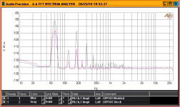
I am not too knowledgeable regarding electronics. Still have a lot to learn. What am I looking at here? I assume the Magenta line is an improvement.
Hi Mike, the chart you asked about is a noise floor comparison, the big spike around 55hz is due to the mains power, then the smaller spikes are harmonics from that. the magenta line indicates lower noise overall.
Six.
Six.
I am not too knowledgeable regarding electronics. Still have a lot to learn. What am I looking at here? I assume the Magenta line is an improvement.
Nice, that is definitely an improvement then. I have since built a DIYPass Nutube B1 Korg which is ridiculously nice sounding. I plan to setup a 2nd system in the somewhat near future. I am going to build a pair of Speaker Design Works - Travelers speakers. When I do that I may incorporate some of these mods to the Adcom GFP-565 and put it on that system.
Thanks for clarification on the graph. I am enjoying leaning so many new things through this hobby.
Thanks for clarification on the graph. I am enjoying leaning so many new things through this hobby.
Our audio shop has closed due to retirement and I would like to share our mod for the GFP-565. I hope that this will help some of you who would like a little better sound quality but the mod will improve clarity first and foremost.
I just wanted to say that this was really generous. I, like some others, am still at the "defective part replacement stage" and really appreciate this huge "download" of information that I am sure has years of experience behind it.
I have a GFP-565 that was messed with and this allows me an amazing shortcut.
Sorry your business closed, best of luck.
@Mikerodrig27
“Change IC201 (IC202) to OPA134 (Change R908 to 12.1k)”
What exactly does this change, and how does it affect operation of IC203/204?
Thanks.
“Change IC201 (IC202) to OPA134 (Change R908 to 12.1k)”
What exactly does this change, and how does it affect operation of IC203/204?
Thanks.
The OPA134 V+/V- is a maximum of 18 volts. I prefer not to operate the rail voltages at max so the R908 will lower the rails to about +/-17 volts. If one uses the OPA604 the rail voltages are 24 volts so need to lower R908 value and it can stay at 12.7k. I like the OPA604 myself and prefer it over the OPA134.
Thanks. This is what I suspected. I’ll get a couple of the opa604’s to try out.The OPA134 V+/V- is a maximum of 18 volts. I prefer not to operate the rail voltages at max so the R908 will lower the rails to about +/-17 volts. If one uses the OPA604 the rail voltages are 24 volts so need to lower R908 value and it can stay at 12.7k. I like the OPA604 myself and prefer it over the OPA134.
- Home
- Source & Line
- Analog Line Level
- ADCOM GFP-565 Preamplifier Upgrade