Before trying to figure out how to match/measure, you need to first put yourself into the problem of having enough devices to match. Have you already bought your JFETS? These are practically impossible to get anymore other than a very small number of shrinking sources.
Look further down the datasheet to Threshold gate voltage (Vgs(th))
Look further down the datasheet to Threshold gate voltage (Vgs(th))
I match the R100's as a matter of course while I am testing for high frequency
distortion, which is variable I am most interested in.
In a channel at 1W / 20 KHz into 8 ohms, they vary between 0.05% and >0.2%
Fortunately only a minority are in the high category.
distortion, which is variable I am most interested in.
In a channel at 1W / 20 KHz into 8 ohms, they vary between 0.05% and >0.2%
Fortunately only a minority are in the high category.
Take my words as a friendly advice :
Attempt something simpler and lower cost before you go for these projects with unobtanium devices.
For example :
http://www.firstwatt.com/pdf/art_amp_camp_1.pdf
When you have learnt all the skills associated with such builds, you can then consider some more costly ones.
Best regards,
Patrick
Attempt something simpler and lower cost before you go for these projects with unobtanium devices.
For example :
http://www.firstwatt.com/pdf/art_amp_camp_1.pdf
When you have learnt all the skills associated with such builds, you can then consider some more costly ones.
Best regards,
Patrick
Speaking of simple amps:
At least one forum member has enjoyed using the unobtainium SemiSouth devices in his ACA. His write up starts here, ACA amp with premium parts. We've been trying a few different Mosfets in the Q1 and Q2 positions, because, why not. The ACA circuit is an easy one to play with.
A couple of us are also looking at a newer CREE part, the C3M0160120D. It looks like it may share some similar characteristics, except that is is readily available for about $5. Yay for that!
The R100 is available but expensive. Just trying to be sure that if matching is important I don't spend big bucks on unmatched parts.
Patrick, I guess the risk you refer to is about blowing the expensive parts? It's just that even PSU components have to be imported to India. So if I'm going through that hassle might as well build this. I will check and double check and triple check the wiring before powering up stuff.
Patrick, I guess the risk you refer to is about blowing the expensive parts? It's just that even PSU components have to be imported to India. So if I'm going through that hassle might as well build this. I will check and double check and triple check the wiring before powering up stuff.
slow as a snake.....
After 8 years trying to make nearly perfect J2......
You see in the first picture the state in the last years, h2 over h3 is o.k. with around 12-14dB higher.
But since the program Diana is published and we can see the residual as well, I saw that I have h2 with positive phase, second picture.
After some fumbling today with the source and drain resistors between the Semisouths I finally got the negative phase....what a moment!
Picture three.
The four SS were bought some time ago from Semisouthfan, as quartets. It seems they had greater differences in transconductance than I thought.
Now I must elaborate how the OLG changed, because the sound depends a good deal how much loop gain (difference of OLG and CLG) exists.
Maybe I have to change the feedback resistor and the CLG value.
I can only recommend to check your builds with Diana.
Attachments
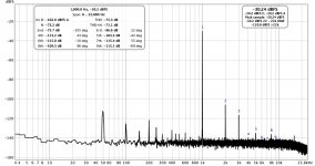
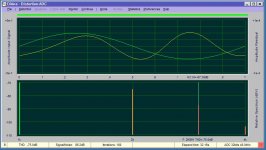

Yes, I use Diana for the residual and phase presentation and the REW for the distortion pattern. REW has more functions and the better presentation of the THD pattern itself.
As you know, I suppose!

Soundcard is a Focusrite Scarlett.
As you know, I suppose!
Soundcard is a Focusrite Scarlett.
Last edited:
Indeed! I need to have a look at Diana - seems like a very nice solution. I ask because I noticed the higher order harmonic details looked very similar to my build of ZM’s babelfish J2 and I was unsure how much my sound card (Focusrite Solo) was at play.
Your measurements and discovery are impressive - well done!!
Your measurements and discovery are impressive - well done!!
REW has more functions and the better presentation of the THD pattern itself.
Please excuse the OT question:
How did you get REW to show the amplitudes of the harmonics in the distortion panel in dB? I use V5,19 and I only get %. I can't find a setting to change from % to dB.
If you click in the setting panel at top right of RTA screen, you should see a ‘distortion settings’ button. It’s in there. If you don’t see/have it, might be worth updating to the latest build

A quick question regarding the size of the heat sinks for the cloned J2 amp boards from Jeff. I have got the PCB printed but the size is around 365mm and hence thinking of cutting board near the led/resistor limiting side and make it more manageable 295mm as this is more in-line with regular 300mm depth cabinets 🙂
Now what sized heat sinks are better for J2? I have spare 300D/150H/83W mm sized heat sink pair as well as 300D/120H/40W or 300D/120H/50W ones are good enough using a 18v 350VA dual secondary transformer?
Thanks for any feedback considering I have procured all the critical parts for my build and wish you all a merry Christmas 🙂
Either the first or the second, by what I learned from mine. The first is a more than enough... the second is probably a little light, the third is not sufficient.
Thank you, I will probably go with 300/150/83mm sized heat sinks and try to build a cabinet around this as with the chopping off the J2 pcb boards gives me lots of cabinet options 🙂
Also going with a 0-18v 9.7A + 0-18v 9.7A and around 350VA transformer.
Also going with a 0-18v 9.7A + 0-18v 9.7A and around 350VA transformer.
Last edited:
I wrote that wrong, number 2 has less area. Be careful how close to the sides/top/bottom of the heatsink you have a device. In other words, if you have a device close to an edge, you will not get even heat dissipation and indeed could get less that what you require and possibly overheat. I don't know how much sink area to an edge you need around the device.
I wrote that wrong, number 2 has less area. Be careful how close to the sides/top/bottom of the heatsink you have a device. In other words, if you have a device close to an edge, you will not get even heat dissipation and indeed could get less that what you require and possibly overheat. I don't know how much sink area to an edge you need around the device.
Thanks, yes I have decided to go with the first option which is 300/150/83mm sized big heat sinks which does the service for my VFET as well as USSA-5. They seem to be more than sufficient as they worked fine with my earlier Aleph J as well 🙂
- Home
- Amplifiers
- Pass Labs
- FirstWatt J2