I chose the 8ohm version because I plan to use it with an active crossover and thought the solitary 8 ohm driver would present a better load to that amp.
I teeter between a transmission line, PRs and a port. I am leaning to prototyping a port first as I consider a down firing external port could be built into the speaker stand and avoid the folding of an internal port.
Still to choose a tweeter but for the cost a HDS is looking good, I have used these before with a waveguide and they probably will work well.
Lots of fun, can't wait 'till they arrive.
If active then 8ohm tweeter is fine - also gives you room to use almost any brand as long as bandwidth is good to do the higher 3k5 kHz crossover.
Ported designs will not be as low distortion due to compression and port harmonics of such a long port.
Ported designs will not be as low distortion due to compression and port harmonics of such a long port.
I have my TL up and running now and it sounds amazing!
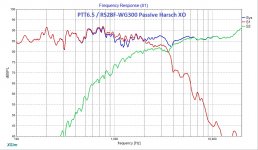
Use Harsch crossover with Purifi as fullrange and Dayton RST28F in WG-300 crossed at 4458khz.
Never had better sound!
Use Harsch crossover with Purifi as fullrange and Dayton RST28F in WG-300 crossed at 4458khz.
Never had better sound!
I run a mix now with TPA3251 on top and TPA3255 on low 3e Audio.
All with OPA1656.
Active with nanoDigi and two Khadas DAC's.
All with OPA1656.
Active with nanoDigi and two Khadas DAC's.
Solve, how do you find the Nanodigi and Khadas, I have an 8 channel set up using that and it does a very good job imo.
Solve, how do you find the Nanodigi and Khadas, I have an 8 channel set up using that and it does a very good job imo.
Yes the nanoDigi doing a good job but the plugin could be better with more PEQ and memorys.
But I think the isolated SPDIF input and outputs is a great thing to remove uggly things in the signal to Khadas so it's no hum or noice.
And I never goe back to an standard LR4 crossover after I got Harsch to work.
So much better in spatial like that sound speakers "disappear".🙂
Solve, agree, my set up seems to really quiet even playing through powered studio monitors. Nice clean sound. Also agree could do with more filter slots but if you combine the individual channels plus the main left/right input for a stereo speaker you have 15 slots. I tend to use the individual channels for peak/trough smoothing and the main left/right for overall shaping.


I have my TL up and running now and it sounds amazing!
Use Harsch crossover with Purifi as fullrange and Dayton RST28F in WG-300 crossed at 4458khz.
Never had better sound!
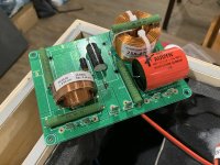
Nice work! Do you have any photos?
Congrats on your great sound!
Still have some work to do but wait until spring to do outside work.
The Harsch crossover at 4458Khz and Purifi running fullrange with no delay on HF works great for me.
The Harsch crossover at 4458Khz and Purifi running fullrange with no delay on HF works great for me.
Attachments

Nice work, Solve!
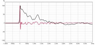
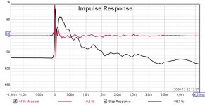
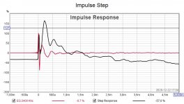
I am a little bit puzzled why the step response falls off in 2-3ms when it looks like your bass extension goes to about 30Hz. 30Hz should be about 33ms long triangle on the step.
Btw, with a higher XO and the waveguide, you should not need any delay in the DSP. That’s why I was able to do it with a passive XO.
Can you please show us the measured XO plot? Woofer by itself, tweeter by itself, and combined system. We should see the combined response dip a little below the woofer ear the XO. We should also see a rise of 55deg a little to the right of 5460Hz.
Last edited:
When you describe the use of the Purifi 'full range' do you mean entirely crossover less, as in nothing in the path?
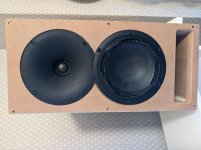
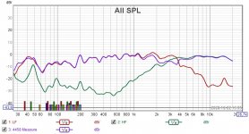
I decided to start over again and now it not looking so good anymore.
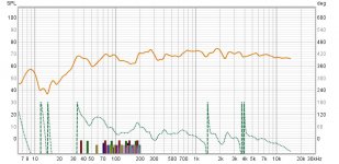
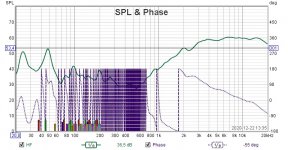
Measure 50 cm middel of LH+HF.
LF no eq no crossover.
HF eq to straighten and match LF lower output and 4458 Bessel no delay.
What to do next?
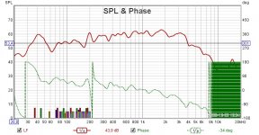
Measure 50 cm middel of LH+HF.
LF no eq no crossover.
HF eq to straighten and match LF lower output and 4458 Bessel no delay.
What to do next?
Attachments
Hi Solve,
To get Harsch, you need 4th order electro acoustic slope. Note that Purifi has natural 2nd order roll off at 3.5kHz. Now apply electrical low pass 2nd order at 3.5kHz and you will get 4th order. Now apply 2nd order high pass on tweeter circa 3.5kHz. You may need EQ to shape it.
The best way to do this is to measure the raw, and use the DSP simulator in REW to test these out. Otherwise trial and error will take a long time and never get quite close. Even though it’s easy to change, remeasuring takes time. Whereas simulating in software is quick and precise. Then transfer the DSP settings to hardware.
You can also do this on Xsim and then transfer the filter to DSP implementation.
Measure on woofer axis as that gives proper delay. No delay is needed unless you like to listen with tweeter on top.
You will notice you have baffle step. So a shelving filter needs to be applied to bring up the bass. I did this with a resistor parallel to the inductor. Here, use a high frequency shelf about -5dB, Q=0.5, circa 900Hz on the Purifi.
The tweeter is very sensitive and will need significant attenuation to get to 84dB. Just plain padding resistor or level attenuation. It needs at least a -12dB/oct high pass though to keep distortion below 2kHz from being and issue.
Good luck!
If you look at your raw woofer data, note the natural roll off at 3k5. That’s the clue to use BW12 at 3.5kHz to get BW24 overall.
Alternatively, you can buy the relatively inexpensive parts for the passive XO and have a nice result that I worked to get right so you don’t have to. But if DSP active is the way you want to go then that’s fine.
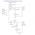
XO:
The air core could be replaced by much less expensive iron core and probably sound fine. More bass actually as DCR is lower. P2P construction could certainly be used here.
To get Harsch, you need 4th order electro acoustic slope. Note that Purifi has natural 2nd order roll off at 3.5kHz. Now apply electrical low pass 2nd order at 3.5kHz and you will get 4th order. Now apply 2nd order high pass on tweeter circa 3.5kHz. You may need EQ to shape it.
The best way to do this is to measure the raw, and use the DSP simulator in REW to test these out. Otherwise trial and error will take a long time and never get quite close. Even though it’s easy to change, remeasuring takes time. Whereas simulating in software is quick and precise. Then transfer the DSP settings to hardware.
You can also do this on Xsim and then transfer the filter to DSP implementation.
Measure on woofer axis as that gives proper delay. No delay is needed unless you like to listen with tweeter on top.
You will notice you have baffle step. So a shelving filter needs to be applied to bring up the bass. I did this with a resistor parallel to the inductor. Here, use a high frequency shelf about -5dB, Q=0.5, circa 900Hz on the Purifi.
The tweeter is very sensitive and will need significant attenuation to get to 84dB. Just plain padding resistor or level attenuation. It needs at least a -12dB/oct high pass though to keep distortion below 2kHz from being and issue.
Good luck!
If you look at your raw woofer data, note the natural roll off at 3k5. That’s the clue to use BW12 at 3.5kHz to get BW24 overall.
Alternatively, you can buy the relatively inexpensive parts for the passive XO and have a nice result that I worked to get right so you don’t have to. But if DSP active is the way you want to go then that’s fine.
XO:
The air core could be replaced by much less expensive iron core and probably sound fine. More bass actually as DCR is lower. P2P construction could certainly be used here.
Attachments

Last edited:
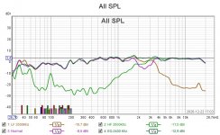
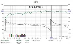
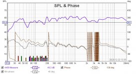
Your measured woofer low pass appears to be second order still? Hence, appears to be symmetric LR2-like and has a dip at the XO frequency. Try 4th order electrical. It needs to fall off steeply at 24dB/oct. please plot data with 5dB major tick marks and zoom in to show more detail.
Aim for a qualitative shape like this:
Steep low pass and shallower high pass.
Aim for a qualitative shape like this:
Steep low pass and shallower high pass.
Attachments
Last edited:
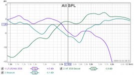
I think you need to measure the raw responses of the woofer plus tweeter plus combined and save as .FRD file. Record data with 6 cycle FDW setting. Save as 1/48th octave smoothing if needed. Export into Xsim. No filters on anything - just raw. Measure 0.5m away on woofer axis. Do not touch speaker or mic during measurements. Only change electrical connections. Post the FRD files and I can help you.
Right now there seems to be a lot of ripples in your data. Make sure mic is about 1m above the floor. So elevate speaker until this is satisfied. We have too much room effects in your signal obscuring the ideal response.
Although your speaker should theoretically measure just like mine.
Right now there seems to be a lot of ripples in your data. Make sure mic is about 1m above the floor. So elevate speaker until this is satisfied. We have too much room effects in your signal obscuring the ideal response.
Although your speaker should theoretically measure just like mine.
- Home
- Loudspeakers
- Multi-Way
- Simple Passive Harsch XO Using PTT6.5 and RS28F in a Waveguide