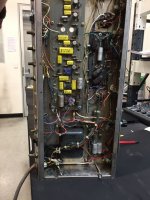
Hi , I recently bought a musicman hd130 guitar amplifier ....I bought it as a challenge as the board had been disconected and it was operating as a slave with its source coming from an external preamp ...
It also had a vox ac30 output transformer fitted to it which was strange to say the least....so the way i went about it was to turn the voltage multiplier into a bridge rectifier and use it as 360vdc supplying 4 6v6gt tubes which is a better choice than the original 4 x el34 with a plate supply of 720vdc
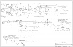
that part of the unit is fine now and ready to go but the problem lies with the preamp section ( see schematic picture )....i'm getting 62vdc at the supply onto the board which is regulating at 31-32vdc .....
Here is the issue I cant get an audio signal past any of the LM307H I'Cs....i dont have a tone generator or an oscilloscope so the best I could come up with is an ipod pluged into a channel and using a coupling cap plugged into another amp I followed the signal path until it ends ..... and it ends at the LM307H chips
And what is the function of the two diodes before entering the 307's ...
I may have overlooked some issue here , why would all the LM307H be dead ? as I tried each one in the first slot in channel one and not one let a signal through ?
Can anyone suggest a better way to test the board with what I have , it would seem the LM307's are dead and is 31vdc the right operating voltage ?
How would I test the IC with a multimeter ?
Since the LM307's are outdated and not highly regarded I was going to substitute these units with NE5534 as others have as there are no LM307H available in Australia.
I would love to hear from someone who has had some experience with these matters.....as a tube amp builder I do ok but as these I'Cs go I'm quite a novice at this point
It also had a vox ac30 output transformer fitted to it which was strange to say the least....so the way i went about it was to turn the voltage multiplier into a bridge rectifier and use it as 360vdc supplying 4 6v6gt tubes which is a better choice than the original 4 x el34 with a plate supply of 720vdc
that part of the unit is fine now and ready to go but the problem lies with the preamp section ( see schematic picture )....i'm getting 62vdc at the supply onto the board which is regulating at 31-32vdc .....
Here is the issue I cant get an audio signal past any of the LM307H I'Cs....i dont have a tone generator or an oscilloscope so the best I could come up with is an ipod pluged into a channel and using a coupling cap plugged into another amp I followed the signal path until it ends ..... and it ends at the LM307H chips
And what is the function of the two diodes before entering the 307's ...
I may have overlooked some issue here , why would all the LM307H be dead ? as I tried each one in the first slot in channel one and not one let a signal through ?
Can anyone suggest a better way to test the board with what I have , it would seem the LM307's are dead and is 31vdc the right operating voltage ?
How would I test the IC with a multimeter ?
Since the LM307's are outdated and not highly regarded I was going to substitute these units with NE5534 as others have as there are no LM307H available in Australia.
I would love to hear from someone who has had some experience with these matters.....as a tube amp builder I do ok but as these I'Cs go I'm quite a novice at this point
Attachments

Concentrate on channel 1 - the FIRST LM307H .
18V+/- is the limit for them that's pin 7 and pin 4 so no more than 18 volts DC on each one to earth.
You need a 1Khz tone applied to the input at say a volt and you should get a voltage reading at the output pin 6 .
Download a 1Khz tone from
Download Audio Tone Files
or many others and use that to apply the sine wave signal.
If its dead at the output then replacement with a more modern audio IC is the answer but I notice you have the old fashioned version ( LM307H ) not the DIP type so its not just a case of slotting it in .
hi again , I measured the voltage at the end of each zener diode and got 1.5 vdc .... and equally .75 vdc from earth to each end respectively... should I have expected 16v neg and 16v pos ?
Im getting plenty of volts at the front of the 620 ohm resistors (62vdc) but only 1.5v after them with the chips pulled ....
I wish I had a better head for this ....
This amp runs at a high power and low power function by actuating a second tap in the primary winding at the main power transformer , so the power going into the board can vary between 62vdc and 85vdc...
hi again,I've change the zenners and no change , still only 1.5vdc ...I've checked that everything is connect in the right spot and it is..
The voltage going into the board is 62 vdc (in the low position) where as on the schematic it shows 42vdc....
The ac going into the doubler is 25vac , which should give me about 70vdc but allowing for inefficiency would give me the the 62vdc that I get now ..
So what gives ???
Im sure the LM307 are not meant to run on just 1.5 vdc-
Would someone look at the voltages across the zenners and tell me what I should be getting ?
I can't see anything wrong apart from the high voltage supply ....
😕
Well after a lot of why is it so I finally found the fault ....they were obvious and dumb ....the previous owner had replaced the zenner diodes ....and put them in back to front.....and when I put the new ones in ..... wel , monkey see monkey do !!!!!
Well I turned them around and got the right voltages ......found one dead LM307H and replaced it with an ne5534 and everything is all good now...
Happy now , a 6v6gt musicman amp ready to rock .....
Well I turned them around and got the right voltages ......found one dead LM307H and replaced it with an ne5534 and everything is all good now...
Happy now , a 6v6gt musicman amp ready to rock .....
Good to hear all is wel now.
But,
What did you learn?
I hope something...
My teacher, half a century ago told me a few things.
I still practise them every single day.
One of them is:
First look at the amp, components, wiring.
If something is not right, find out why.
Then, and only then, replace the part or parts.
AND, make notes, plenty of notes.
You have time, do not hurry.
It makes repair and life easier.
and keep that other arm on your back...
You may want to fit some local supply bypassing on the '5534. It has a lot more bandwidth than the venerable LM307H; in its day, it was considered unnecessary for each individual op-amp to have its own personal energy store.
The back-to-back diodes across the op-amp inputs are for overload protection and recovery. An op-amp in an amplifier circuit that is operating normally, will have both inputs within millivolts of each other at all times. Maintaining that is its job.
Oh, and if a schematic shows "16V" next to a zener, that's usually the voltage to expect across it.😉
Glad you had success!
but wait !!!
But wait there"s more ......
It goes like this.....I can hear that the tubes have plenty of headroom and drive but it seems the preamp is distorting earlier than it should and not driving the 12ax7 as well as it should ....
Ive remade the amp as a 30 - 40 watt , 6v6 tube amp and in the real world this is more than enough ....but this amp was designed to produce 130 watts ....so the clean that I get from the preamp was was probably enough to be loud enough when feeding into a 130watt slave ...
So here is the problem how do I make the preamp drive a little cleaner and harder ?
The preamp begins to slightly distort at 3.5 on the dial and on ten is quite loud but with too much distortion ....but at 3.5 on the dial its outputing about 5 watts from the tubes , but i feel that even at max volume the tubes still have more to offer ...perhaps the first IC in the stage can be tamed and the second be have its gain / output / drive increased ?
Barring this it may seem easier to ditch the opamps and go tube all the way ....at least i can say with certainty that will be effective but what a shame to waste this vintage componentry ....😕
With the modifications already described, you may need to buy or borrow an oscilloscope to address the problem thoughtfully. But a couple things do come to mind ..
- The 620 ohm resistors that supply the zeners may be stretched from having had 15 extra volts across them for however long that was. Check that your +/-16V rails aren't sagging at higher gains.
- The 12AX7 may be tired. Put one hand in your pocket and carefully measure the quiescent voltages around the 2nd stage. It's a little unusual (by my experience, anyway) to expect a 12AX7 to drive 4 output grids directly. Usually they're in lower-current/higher-gain stages.
- Have you made the proper adjustments to the global feedback path? You mentioned an AC30 transformer -- isn't that going to have changed the overall gain?
- You didn't say which of the 4 gain pots you're setting to 3.5 -- remember, a valve preamp may happily tolerate mis-stacked gains, op-amps will not.
- Before discarding the existing preamp, try adding some gain (voltage and/or current gain) between the last LM307H and the 6V6 grids. At least it would be much easier, cheaper, and faster than designing a whole new preamp.
My money is on something untoward in the power amp -- incorrect bias or global feedback, stretched resistors upsetting DC operating points, incorrect screen voltages for the new tubes, etc.
Cheers
Last edited:
The 12AX7 -aka ECC83 has a warning in my Mullard industrial manual quote-
When operating this valve (tube ) with grid current bias and a HIGH source impedance ,the second harmonic distortion rises to a peak at quite LOW levels of output (about 10V RMS and then falls with increasing drive .
The third harmonic then begins to rise finally reaching 5% at a much higher output level than with zero source impedance --etc.
I have distortion values at various plate voltages including suggested K(cathode ) resistors /plate resistors /grid resistors .
While this tube is used extensively in tube audio Mullard designed the ECC82 as an AF amplifier from the start and the warnings for the ECC83 don't apply to the ECC82.
thanks for your reply Rick, and seasons greetings to you and yours....in regards to the output tube setup I have not reconnected the feedback to the driver tube ...I thought to evaluate it before I go further with that ....I have no oscilloscope to use so its mostly trial and error
The 12ax7 is fairly common in guitar amps, I'd say 90% of all guitar amps use them from start all the way through to the phase inverter....
However you do see greater variation in hifi units though
Because I'm always making various tube amps I have testers etc and so all the tubes used are balanced and equal , although the phase inverter tube needs not be balanced as it utilises the boot strapped cathodyne style ...
The resistors you mentioned read 640 and 670 ohms perhaps a little imbalance however the zenners I used are 15v types , so would 1 volt make this much difference ?
as I mentioned before it starts to distort at around 3.5 on the dial ....this is the volume pot after the second IC on each channel ....the master being related to the 12ax7
These preamps are supposed to distort at some point as distortion is a desirable thing with guitar amps but in this case I would expect a little more gain before breakup occurs....could IC lm307h in position 7 be a bit part of the breakup issue ? as this is where gain control occurs...It never occurred to me to swap it with another until just now ...........DOH !!!
Even with the master turned way back it will still distort heavily at low volumes but I must say the clean from the ne5534 is nicer than the 307h
Anyhow , thanks for your help its always appreciated , cheers 🙂😉
While this tube is used extensively in tube audio Mullard designed the ECC82 as an AF amplifier from the start and the warnings for the ECC83 don't apply to the ECC82.[/QUOTE]
I did consider using a 12au7 in place of the 12ax7 and then adding a 6c4 tube in the gain stage.....12ax7= U100 ...12au7 and 6c4 U20 x U20 = U400 ?
the cathodyne PI would suit the 12au7 better than the 12ax7
I did consider using a 12au7 in place of the 12ax7 and then adding a 6c4 tube in the gain stage.....12ax7= U100 ...12au7 and 6c4 U20 x U20 = U400 ?
the cathodyne PI would suit the 12au7 better than the 12ax7
And bear in mind that due to their much lower gm your 6V6's provide much lower gain than the original EL34's.
Best regards!
Best regards!
yes the amp came with a matched set of rft el34's and a drake "ala" vox ac30 output transformer (30 watts rms ) instead of the original 130 watt output transformer ....since it had octal sockets in it already then it just seemed dumb to replace with el84 tubes ....6v6 seemed the logical choice....4 x 6v6 = 30 - 40 watts , instead of using the 720vdc I just converted it to bridge rectifier and got 360vdc , which is optimal for 6v6
I am a musician , a guitar player and the amps i use mainly are of the 18 to 30 watt types...these amps sound best when run at 80 to 90 % of there output.
I had a fender 100 watt amp and I could never get it past 3 on the dial ...if I did it would drown everyone out ......so it was too much amp !!!! I got rid of it.
I think what Im doing is right but i have to sort out this preamp issue though
they originally produced 130 watts !!!! , this power would be useless!!!
I think if this amp was running 130 watts then with the preamp dialed at 3 it would be loud enough ....thats if I was to assume it correctly ...perhaps...
Most of the youtube demo's i've seen have the cleans dialed in at 3 - 4 and master on fullish...its possible the 130watts was more about compensation than loud ....😱🙄
Yes, I understood what you've done and out of which reasons. Anyway, mind to notice that the EL34's gm is almost three to four times as high as the 6V6's, which translates to that your modified amplifer needs more drive signal even with the same output power, say 30 watts, than if it were equipped with the original EL34's.
Of course I know that gm doesn't tell everything about voltage gain (plate load and internal plate resistance come into account, too), but it's just a clue. And I might as well not be right, hence didn't exclude an actual issue with your preamp.
As others yet said: Tracing each stage's gain in order to nail down an issue requires a signal generator (a simple one at least) and an AC voltmeter or o'scope.
Best regards!
When operating this valve (tube ) with grid current bias and a HIGH source impedance ,the second harmonic distortion rises to a peak at quite LOW levels of output (about 10V RMS and then falls with increasing drive .
The third harmonic then begins to rise finally reaching 5% at a much higher output level than with zero source impedance --etc.
Note that this explicitely relates to grid current bias, not to cathode bias, is quite understandable and applies to grid current biasing of any tube. The fact that this hint was omitted in the ECC82/12AU7 data sheets indicates that this tube was _not_ primarily dedicated as an AF tube.
Btw, I'm quite surprised from noticing in the OP's schematics that this HD130 has a 12AX7 PI tube. I would have expected sort of a cascode arrangement with a pair of BJT's driving the 6CA7's cathodes and a pair of opamps doing the PI job.
Best regards!
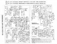
hi , this schematic is fairly close to what I have done ....this one has 30vdc more than what I have....on my amp I have a 5w 470 ohm and a coupling cap 100uf on each cathode .... this is a kit available from ted webber speakers...its rated at 40 watts...
Attachments
rifraf,
surely I didn't want to offend you, as the schematics in your 1st posting appears to be original. I'm scratching my head anyhow. Maybe that MM later switched for the designs with only the power tubes left?
Btw, I well remember Mother' Finest's first appearance in German TV in 1978. They were rather unknown here previously, but ignited by this gig gathered huge following all over Europe. Their bassist Jerry Wyzard Seay played his Alembic through two HD130 heads. WHAT a sound!!!
Best regards!
- Home
- Live Sound
- Instruments and Amps
- Musicman Preamp woes !!