Im not offended at all Kay , this is not the tube amp section so I expect this may not be the place for tube topology .......its more about the op amps...
it would seem they are cascading ... the first two seem to amplify cleanly then depending on how much gain you place on IC number 7 is how much it will get over driven...I could be wrong though..
so would an alternative chip be capable of handling the excessive drive....I wouldnt know where to start looking or it anything like that exists
you could imagine if we rolled between 12ax7 and 12au7 the gain difference..
perhaps TL071 or TL072 ....a shot in the dark ?
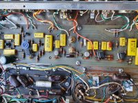
The preamp section basically consists of three gain stages for both channels: The first stages' gain is 23, the 2nd stage's is about 6 in the 1st channel and about 5 in the 2nd one, the adder provides a gain of about 20. As there aren't diodes or other devices to add some distortion, this design exclusively relies on the LM307's distortion, which some may like, others not so. If you replace these with other single (!) opamps, the amplifier' total sound surely won't be the same anymore.
Best regards!
Best regards!
It doesn't really matter that the sound dynamics become different from the original style that musicman had originally employed .... in the 130 watt version there may have been sufficient volume to operate sufficiently ...but in this 30 /40 watt version what would work better is if the preamp was clean at 80% gain employed with enough gain to drive the tube section ...
If there is no mod that can be adapted to chip 7 so as to allow it to drive cleanly , by either IC substitute or component change then I could bypass it and install another tube gain stage otherwise it would be useless to me at a gig level ... I would prefer to save the board if I can , that way I can utilise the reverb and vibrato ...
I guess this is what I was really asking ... I figured the solid state section of DIY audio would seem a better place to ask these questions ...
You can click on the little '!' with a red triangle around it, bottom left corner, if you want a Moderator's help moving it. Imho it's good here: The solid state problem is already solved.
Please, don't tear anything out yet. You mentioned a 470R cathode resistor on the 6V6's -- what's the DC voltage across that? That seems like an awfully large value to me. Do you have all 4 sockets occupied, or just 2 6V6's? How about voltages on the 2nd 12AX7 stage?
Even without an oscilloscope or proper signal generator, there are lots of operating point measurements that you haven't yet reported. If we can get those sorted, it will be time to take advantage of some of the online resources for test signals.
Sure sounds like a power amp problem from the symptoms you're reporting; bet Kay Pirinha's note about the 6V6's having much lower gain is dead on. Also suspect your 6V6's are operating too near cutoff.
As for gain improvements, maybe start with a Cathode bypass capacitor on the 1st 12AX7 stage. That is something notably different than the Weber schematic you posted, and the phase splitter cannot provide gain without wrecking symmetry.
This'll be a nice bit of kit when you get it going. Don't give up too easily.😉
Regards
Last edited:
99% of MM amps use their unique cascoded or cathode driven power amps: tubes work in Class AB2 , no typo, grids are STRONGLY biased POSITIVE, to the tune of +22 or +24V or so, can gobble as much current as they want , so every last bit of current is sucked out of those cathodes,and actual current passed is whatever´s fed those cathodes by series transistors.rifraf,
surely I didn't want to offend you, as the schematics in your 1st posting appears to be original. I'm scratching my head anyhow. Maybe that MM later switched for the designs with only the power tubes left?
It gives a unique sound: LOUD, CLEAN and LOUD 😀
This particular model posted above is the white fly, black sheep, you name it, where they bowed to "conventional" designs demands.
A total failure, they pleased nobody, and quietly dopped it.
"Music Man" only in the label, not the spirit, by any means.
Downgrading it to low power 4 x 6V6 conventional tube PI and bias won´t damage it any further, so do as you wish, just don´t expect any "Music Man Sound" out of it.
Please, don't tear anything out yet. You mentioned a 470R cathode resistor on the 6V6's -- what's the DC voltage across that? That seems like an awfully large value to me. Do you have all 4 sockets occupied, or just 2 6V6's? How about voltages on the 2nd 12AX7
As for gain improvements, maybe start with a Cathode bypass capacitor on the 1st 12AX7 stage. That is something notably different than the Weber schematic you posted, and the phase splitter cannot provide gain without wrecking symmetry.
#############
Hi again , all 4 sockets are occupied ... I measured the voltage across all the cathode resistors and got just on 20vdc on high and 13vdc on low settings (plate voltages of 360 and 250 vdc)
On the gain stage of the 12ax7 the cathode is measuring 1.6vdc .....there is no bypass cap on this as it is still in its original MM format...same topology differing values to the Webber...
The value of 470 ohms would be too high a value if all four cathodes were attached but in this case I have gone the safer option of having a resistor for each tube so that if one fails the others remain stable ...the one and only drive from the single triode seems to be where it should be...
I'm not giving up on the board , I think there will be a way around this I'm sure
I went to do an A/B with the LM307 on IC number 7 but when I pulled it out I couldn't get another one to go into the holder....I messed with it a bit but just ended up bending pins so I guess I'll be upgrading that one as well ....
And so the stone rolls
Last edited:
Thats a problem I have encountered many times due to the IC sockets of those old IC,s "stiffening up " due to "metal aging " ( molecular change in the composition ) .
A grid bias of -20 V, as per the voltage drop at the four individual cathode resistors, appears to be ok with a plate supply voltage of 360 V.
It's hard, at least for me, to trace down the issue you have without measuring the signal with an o'scope. Maybe the amplifier works correct and you just _think_ there's a bug?
Best regards!
It's hard, at least for me, to trace down the issue you have without measuring the signal with an o'scope. Maybe the amplifier works correct and you just _think_ there's a bug?
Best regards!
Though it may be safer for the tubes, 1:1 / cathode:resistor, may not please the output transformer. Some do not well-tolerate DC imbalance so happily -- you may have some saturation.
The reason I wondered about the phase splitter voltages is, it seems a tall order for a 12AX7 to be trying to drive four big power tube grids -- especially at the thin currents likely resulting from the 1k5 Cathode bias resistor.😉
Have you downloaded the test tones yet? We can get some rough idea of gain shortcomings by measuring AC voltages if you have a way to supply a steady signal.
Cheers
Last edited:
Any big Marshall tube amplifier drives it's two or four EL34 grids directly from the ECC83 PI.
Best regards!
Best regards!
Wow! Alright then .. good to know. Thanks.
Can't remember and too lazy to look it up: Does the EL34 grid have lower capacitance than the 6V6? Was guessing it was.😉
Regards
Can't remember and too lazy to look it up: Does the EL34 grid have lower capacitance than the 6V6? Was guessing it was.😉
Regards
Surely not, as the EL34's internal structure is much bigger and the grid to cathode distance and/or grid wire pitch most probably are smaller than in a 6V6.
Best regards!
Best regards!
in conclusion....
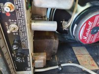
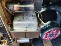
Hi folks well the board stayed close to where it was as before ....I did some replacements on three of the old TO-99 sockets and taste tested the chips to see what could be done without too much effort...one channel I left untouched and the other , chip one is a NE3354 , chip two is a LM301 , and they sum into a TLO-71
I must say the new chips sound much better than the older LM307h's
This gave the cleanest result with the most amount of drive ......but the 6V6's were still asking for more , so I installed a 6C4 tube with a modest amount of drive and took the amp from cathode bias to fixed and I'm happy with that ...a few extra volts helps...
I also disconnected the feedback , this gave me some more noise with no significant changes to the tone ...
My feelings are is that the output transformer is a little inefficient .....I put some voltage through it and done the maths and came up with 3.6K.....its in the ball park for 6V6 but being AC30 I thought it would have been 4K....
I would be happy to do my next gig with this amp ....
Maybe this will help another adventurer along the way in future ....
Cheers and thanks for your support, much appreciated having someone looking over your shoulder should help be needed....
Attachments

- Home
- Live Sound
- Instruments and Amps
- Musicman Preamp woes !!