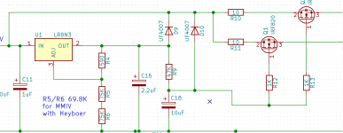
Not sure about this topology, the LR8 like the 317 works by providing a fixed voltage drop between the output terminal and the reference terminal, there is internal temperature compensation that maintains that voltage differential as relatively constant, now you've added about 700mv to that (pass transistor Vbe) which has an uncompensated TC of about 10mV/°C, that is going to result I think (and I could be wrong) in quite a lot of voltage drift due to varying operating temperature of the transistor. (And the drift is scaled by the ratio of your feedback resistors.)
In my implementations I use the LR8 as suggested in the data sheet, use an LPF filter to filter out the not insignificant noise in the output of this device and feed it to an IRF820 which is the pass element. It's quiet, works well and has been reliable over the 4 years or so I have been using this topology. Output impedance is low (determined by the transconductance of the mosfet you choose) and I shunt the source with 22uF - 47uF to ground.
It has a feedback circuit. It not only compensates for the internal heating and so on but since we have a output element and the voltage feedback is taken from it it also compensates based on ooutput voltage. Its not like a resistor. By taking the feedback from the pass element now the output is not dependant on the linearity of the transistor. The current gain chart basically. so the voltage should be more stable with just a transistor hangin in there like a follower or a fet. The fet just completely decouples the output since the LR8 does not notice any difference if the load is 10mA or 1A. It does notice it tho with a BJT since it requires current drive to let current pass trough. But It shouldnt really matter. It should be probably more stable with a fet and feedback because the LR8 would not need to source any current at all, probably rendering it a bit unstable so loading it is a good idea (1mA per say). I dont know really. The circuit is as universal as it gets. I can basically insert a fet in the place of the transistor and it would work. So I can try both.
No its actually two pi radians per second. the Y axis is Joules per second.
Joker 🙂
Quite high output impedance but maybe not so bad compared to only RC networks as done in medieval times. The 5V output is what wonders me though....how does it behave at let's say 250V?!
Last edited:
In my implementations I use the LR8 as suggested in the data sheet, use an LPF filter to filter out the not insignificant noise in the output of this device and feed it to an IRF820 which is the pass element. It's quiet, works well and has been reliable over the 4 years or so I have been using this topology. Output impedance is low (determined by the transconductance of the mosfet you choose) and I shunt the source with 22uF - 47uF to ground.
Like this?
The LR8 in tube circuits – wauwatosa tube factory
Joker 🙂
Quite high output impedance but maybe not so bad compared to only RC networks as done in medieval times. The 5V output is what wonders me though....how does it behave at let's say 250V?!
That takes a bit more interesting setup as the input impedance of the VNA has to be high enough not to affect the measurements. Instead of using a simple cap to inject the current, a transformer. Different probes too.
I am going to make a somewhat educated guess that the LM317L has a higher output impedance than the TO220 LM317 we are used to living with.
I apologize to Kevin for being a pedant, but that's what I was raised to be by a bunch of nuns and Jesuit priests! FWIW, the math works.

This is what I used to power a couple of my recent phono stage designs.
Thanks kevinkr,
So R9 and C18 are forming a LPF here? I'm just a hobbyist so bear with me, so what would be a good cutoff frequency for the LPF? Using a LPF calculator I found on the Internet I calculate 47K with a 10uf LPF gives a cutoff freq of only .34 Hz. Wouldn't a higher cutoff frequency be better? Maybe 70Hz or 130Hz? Not sure where in the spectrum the LR8 makes its most noise.
Anyway I like the circuit, the stereo split is nice.
It's a simple first order filter that attenuates noise at a rate of 20dB per decade (although the ESR/ESL eventually results in a shelf at which point the attenuation stops.)
I chose such a low value in order to delay the rise of B+ and also to provide as much attenuation as possible in such a simplistic circuit.
I chose such a low value in order to delay the rise of B+ and also to provide as much attenuation as possible in such a simplistic circuit.
This is what I used to power a couple of my recent phono stage designs.
That looks nice and easy. Will give it a go.
It's a simple first order filter that attenuates noise at a rate of 20dB per decade (although the ESR/ESL eventually results in a shelf at which point the attenuation stops.)
I chose such a low value in order to delay the rise of B+ and also to provide as much attenuation as possible in such a simplistic circuit.
Nice, very cool.
Impedance of the LR8N3 with a 4.7u aluminum electrolytic on the output, 5V out, 5mA DC current:
A 4.7 uF capacitor by itself is about 0.3386 ohm at 100 kHz, so if the horizontal axis is in Hz and the vertical in ohm, there must be something wrong with it.
A 4.7 uF capacitor by itself is about 0.3386 ohm at 100 kHz, so if the horizontal axis is in Hz and the vertical in ohm, there must be something wrong with it
Most regulators range from 0.01 to 0.001 Ohm, some like Salas in the tens of microOhms.
I ran the test on both the Bode100 and the AP and came up with the same numbers (AP only goes to 200kHz) using the same setup which WJ used for his articles, but dialed the current back a lot owing to the LR8's limitations.
Upon further inspection, it's the output capacitor -- ESR measures 8.3 Ohm @120Hz, 3.7 Ohm @1kHz. I fear that a film cap will cause the regulator to become unstable.
Last edited:
Not taking seriously post #60, you haven't specified the units anywhere. Guessing that you used SI units without prefixes, so that the X axis is in Hz and the Y axis in ohm, you should then see an impedance smaller than 5.02 ohm from 10 kHz onward when the capacitor's ESR is <= 3.7 ohm above 1 kHz. Your measurement shows 14 ohm at 10 kHz and even more at frequencies up to 10 MHz.
All in all, what are the units?
All in all, what are the units?
What I've learned in the past two weeks -- I may have "crushed the butterfly" by using an injected current which was too great.
Hope I have redeemed myself. I reduced the injected signal level to -14 and -18dBm. At this level, the 4.7uF aluminum electrolytic works fine.
Hope I have redeemed myself. I reduced the injected signal level to -14 and -18dBm. At this level, the 4.7uF aluminum electrolytic works fine.
Attachments

Why does the impedance increase a lot below 1 kHz?
The minimum output current of the regulator is 0.5 mA (worst-case) and you have a 1.4 mA DC load current. That means the regulator can handle 0.9 mA peak AC without being driven out of regulation. A 50 ohm sine wave source with -23 dBm available power would deliver almost 0.9 mA peak to a low-impedance load, assuming you somehow prevent DC current from flowing through the sine wave source.
That is, I think you have to stay below -23 dBm when the DC current is 1.4 mA, and you have to ensure somehow that the DC current is not going into the AC source. Then again, I'm making all sorts of assumptions, so maybe this comment doesn't apply to your set-up.
If you need a high voltage constant current regulator, Ixys make several.
Eg 900v 1-100ma. 40w, $3
https://www.mouser.co.uk/datasheet/2/240/DS98729A(IXCP-CY10M90S)-1547388.pdf
Eg 900v 1-100ma. 40w, $3
https://www.mouser.co.uk/datasheet/2/240/DS98729A(IXCP-CY10M90S)-1547388.pdf
At a dynamic resistance of 30k, it's pretty much useless.
For a good current source I want at least several 100k dynamic resistance, preferably a Megohm.
Jan
For a good current source I want at least several 100k dynamic resistance, preferably a Megohm.
Jan
Last edited:
160K more useful?
https://www.mouser.co.uk/datasheet/2/240/98704-1546069.pdf
Better. But you know, it's just a FET + one resistor. It's not that this is 'a part', it's a clever way to present a well known circuit as a part. Creative.
But you get much better results selecting a FET that has better parameters and mate it with a suitable resistor.
Jan
- Home
- Amplifiers
- Tubes / Valves
- Regulating high voltage (up to 450V) has become as easy as a LM317!