A non working Rotel RA-1412 came into my possesion in October. Since then, both power supplies were made to operate normally. Next I intended to check the DC adjustment and bias but ran into a problem or two that I cannot sort out.
Firstly, moving the bias adjustment pot of the left main amplifier board either way does nothing, the meter continually reads 0 milivolts. There are three adjustment pots on each amp board. I removed and cleaned the three on the board in question but no change, rotating the bias adjustment still produces 0mv on the meter display.
Bias on the right channel main amp board is adjustable.
Secondly, the Protect LED lights up unless I disconnect +B and -B from the left main amp board. After that, the amplifier comes out of protection and the right channel operates as it should.
My thought was of a defective component on this left main amp board.
So far I have removed and checked every transistor (some more than once), the one and only diode, measured every resistor (replaced two that were quite under spec), removed and replaced the four electrolytic capacitors, examined the foil side for any solder bridges or bad connections. And as mentioned, removed and cleaned the three adjustment pots.
For what it's worth, the device I have for checking transistors is one of the cheap inexpensive multi-testers from China. It has previously identified bad transistors as a "diode" or "unknown device". All of the transistors on this amplifier board were identified as BJT so by virtue of that, I accepted that they are all OK.
Nothing seemed wrong but connecting that board continually makes the amplifier go into Protect Mode.
What I did next may be thought as silly but it's all I could think of. I have no bench euipment at my disposal.
With power going to the board, I disconnected each and every wire individually to see if disconnecting one of them prevented activating the Protection circuit.
And one of them did - the wire going to pin #5. Which looks, coincidentally enough, like it feeds into the Protection circuit board.
I have yet to expose the Protection circuit board because I cannot dismiss the notion that there is something about the left main amp board that is causing the problem.
If any tips or suggestions come to anyone's mind, they would be appreciated.
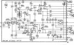
I realize that no one here may be familiar with a Rotel RA-1410 so attached is the schematic of the left main power amplifier board.
The Protection circuit board schematic was too large for the snipping tool so not attached but it's present on HiFi Engine if anyone cares to have a look.
Firstly, moving the bias adjustment pot of the left main amplifier board either way does nothing, the meter continually reads 0 milivolts. There are three adjustment pots on each amp board. I removed and cleaned the three on the board in question but no change, rotating the bias adjustment still produces 0mv on the meter display.
Bias on the right channel main amp board is adjustable.
Secondly, the Protect LED lights up unless I disconnect +B and -B from the left main amp board. After that, the amplifier comes out of protection and the right channel operates as it should.
My thought was of a defective component on this left main amp board.
So far I have removed and checked every transistor (some more than once), the one and only diode, measured every resistor (replaced two that were quite under spec), removed and replaced the four electrolytic capacitors, examined the foil side for any solder bridges or bad connections. And as mentioned, removed and cleaned the three adjustment pots.
For what it's worth, the device I have for checking transistors is one of the cheap inexpensive multi-testers from China. It has previously identified bad transistors as a "diode" or "unknown device". All of the transistors on this amplifier board were identified as BJT so by virtue of that, I accepted that they are all OK.
Nothing seemed wrong but connecting that board continually makes the amplifier go into Protect Mode.
What I did next may be thought as silly but it's all I could think of. I have no bench euipment at my disposal.
With power going to the board, I disconnected each and every wire individually to see if disconnecting one of them prevented activating the Protection circuit.
And one of them did - the wire going to pin #5. Which looks, coincidentally enough, like it feeds into the Protection circuit board.
I have yet to expose the Protection circuit board because I cannot dismiss the notion that there is something about the left main amp board that is causing the problem.
If any tips or suggestions come to anyone's mind, they would be appreciated.
I realize that no one here may be familiar with a Rotel RA-1410 so attached is the schematic of the left main power amplifier board.
The Protection circuit board schematic was too large for the snipping tool so not attached but it's present on HiFi Engine if anyone cares to have a look.
Attachments
Last edited:
Could you attach the left channel to the right channel wiring? This would tell you for sure if it’s the amp board or the protection board or something else. Not familiar with the design so I’m not sure how difficult this would be, but it would certainly rule out the amp board if it works normally on the right channel connections
With the amp in 'Protect' check that the DC voltage on pin#5 is zero. If it is not then that is why the amp is in protect state.
Could you attach the left channel to the right channel wiring? This would tell you for sure if it’s the amp board or the protection board or something else. Not familiar with the design so I’m not sure how difficult this would be, but it would certainly rule out the amp board if it works normally on the right channel connections
That is a bit of an undertaking but it is possible although I'd like to avoid it.
As things are now, I have physically removed the left board and extended each of the 18 or so wires by 12" so that it remains connected but can be manipulated.
With the amp in 'Protect' check that the DC voltage on pin#5 is zero. If it is not then that is why the amp is in protect state.
Checking that produces (-)45 volts at left amp board pin 5.
To compare I measured at pin 5 of the working right amp board and got fundamentally zero volts.
EDIT: FWIW, when I first began tinkering, I found that two of the four left channel output transistors were bad.
Last edited:
Have you checked all driver transistors? And emitter resistors? Assume yes, since those likely were damaged with outputs.
Good news, you have proven the amp still is in need of repair and the protection circuit is doing it’s job.
Good news, you have proven the amp still is in need of repair and the protection circuit is doing it’s job.
Checking that produces (-)45 volts at left amp board pin 5.
To compare I measured at pin 5 of the working right amp board and got fundamentally zero volts.
EDIT: FWIW, when I first began tinkering, I found that two of the four left channel output transistors were bad.
So it seems to be a normal kind of failure mode... as bullittstang says below
Have you checked all driver transistors? And emitter resistors? Assume yes, since those likely were damaged with outputs.
Good news, you have proven the amp still is in need of repair and the protection circuit is doing it’s job.
Exactly 🙂 Classic failure mode.
Post 1 : "I have no bench equipment at my disposal"
You stated using a cheap tester from China. I think it may be "good enough".
It seems to be confirmed that you use a voltmeter also.
Any more ?
You stated using a cheap tester from China. I think it may be "good enough".
It seems to be confirmed that you use a voltmeter also.
Any more ?
Have you checked all driver transistors? And emitter resistors? Assume yes, since those likely were damaged with outputs.
Good news, you have proven the amp still is in need of repair and the protection circuit is doing it’s job.
All of the transistors on the board were removed and checked on my "device" and were correctly identifed as BJT transistors.
All of the resistors on the board were measured and all but two were within spec. I replaced the two that weren't.
Post 1: "All of the transistors on this amplifier board were identified
as BJT so by virtue of that, I accepted that they are all OK".
Post 5: "when I first began tinkering, I found that two of the four
left channel output transistors were bad".
Is this a small contradiction ? Did you replace any transistors ?
Did you keep replaced parts for reference ? Did you use original
replacements ?
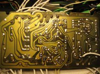
Good picture of both sides of the boards will be useful.
You did not reply to question in post 7 which determines the next step.
Thanks.
as BJT so by virtue of that, I accepted that they are all OK".
Post 5: "when I first began tinkering, I found that two of the four
left channel output transistors were bad".
Is this a small contradiction ? Did you replace any transistors ?
Did you keep replaced parts for reference ? Did you use original
replacements ?
Good picture of both sides of the boards will be useful.
You did not reply to question in post 7 which determines the next step.
Thanks.
Check presence of +BL - is there a fuse ?
Post 1 : "I have no bench equipment at my disposal"
You stated using a cheap tester from China. I think it may be "good enough".
It seems to be confirmed that you use a voltmeter also.
Any more ?
No, that is pretty much the sum of my test equipment.
There are two 5A fuses per power supply board. Those on the left side were missing. I installed new ones.
+BL is near to 60 volts.
You will need to go back at least one transistor from the damage.
So you replaced outputs, did you also check the drive transistors (usually smaller but still on heatsink)? How those measure?
If either of those tested bad, go back one transistor prior and test the pre-driver (or similar). These are usually smaller than the drivers (to-220 or to-92 parts). Did you test those?
You said only two resistors tested bad and you replaced.
Did you test all the diodes and zeners? You might find a couple of those open or shorted.
Just some ideas of where to go next - you obviously have DC so something is shorted or open to allow that to pass straight thru to the speaker.
So B- must be about 60V also (output unloaded).
Output goes strongly negative (you wrote -45V).
- Which transistors did you change etc (see above) ?
- Have these been in sockets so that it was easy to
replace without mixing up wires ?
- Which resistors changed ? Pictures ?
I did not understand it was defective from the beginning.
Missing fuses are a strong hint that somebody gave up.
Original condition questionable then.
Cross reply with post 13..
Last edited:
Related thread is here and adds useful information :
Opinion wanted re subs for 2SD426 T03 output transistors
It seems we have to find out everything ourselves.
Opinion wanted re subs for 2SD426 T03 output transistors
It seems we have to find out everything ourselves.
Post 1: "All of the transistors on this amplifier board were identified
as BJT so by virtue of that, I accepted that they are all OK".
Post 5: "when I first began tinkering, I found that two of the four
left channel output transistors were bad".
Is this a small contradiction ? Did you replace any transistors ?
Did you keep replaced parts for reference ? Did you use original
replacements ?
Good picture of both sides of the boards will be useful.
You did not reply to question in post 7 which determines the next step.
Thanks.
By output transisters I am referring to the TO3's on the heatsink, not transitors on the main amp board. Two of the four TO3 outputs on the left side were blown, the other two are OK. All four on the right side are fine.
But should this main amplifier board/Protection issue get solved, I will replace all eight outputs with eight of the same, modern devices
None of the TO92's or TO22's on the main amp board appeared to be faulty.
The only transistor I have replaced was a TO92 on the left channel power supply.
Topside and underside pictures of the left main amplifier board as requested.
Please excuse the delay in responding. I am the process of making soup for twenty and have a nine month old Labrador to attend to.
Attachments

Now we learned that two power output transistors have been changed
"off board", but we still do not know which two of four and also not your
choice of subs.
Since this is an old-school quasi-complementary amp it may be the upper
or lower half pair or mixed.
If and only if the new transistors are operative and their wires are
attached in a correct way more parts have to be inspected.
But you said that everything on board is fine. So I asked for clear pictures.
Can we be sure that the white wires are attached correctly ? I notice some
caps have been replaced (did you tell?). And a "TO92" transistor somewhere
else, common to both channels or not ?
Checking or adjusting bias on a defective amp is useless. I would however
expect a detectable fault current al least. So another question is : how did
you check bias with a broken amp?
Anyway with your level of communication this can easily go to 50 pages
with no result. But no need to hurry if we only know you are absent.
I can not recommend replacing working transistors of good origin. Rotel
had a better chance to buy quality semiconductors than you have today.
Now we learned that two power output transistors have been changed
"off board",
but we still do not know which two of four and also not your
choice of subs.
Since this is an old-school quasi-complementary amp it may be the upper
or lower half pair or mixed.
If and only if the new transistors are operative and their wires are
attached in a correct way more parts have to be inspected.
But you said that everything on board is fine. So I asked for clear pictures.
Can we be sure that the white wires are attached correctly ?
I notice some caps have been replaced (did you tell?).
And a "TO92" transistor somewhere else, common to both channels or not ?
Checking or adjusting bias on a defective amp is useless. I would however expect a detectable fault current al least. So another question is : how did you check bias with a broken amp?
Anyway with your level of communication this can easily go to 50 pages
with no result. But no need to hurry if we only know you are absent.
I can not recommend replacing working transistors of good origin. Rotel
had a better chance to buy quality semiconductors than you have today.
The two defective output transistors are/were the top pair in the left channel. They are original to the amplifier - Toshiba 2SD426. At some time in this amplifier's life the bottom two were replaced with Sylvania ECG-260's.
The two Sylvania transistors are good.
After some online reading, it appeared to me that those Toshiba's and the Sylvania's are one and the same transistor.
The four on the right channel are all original Toshiba 2SD426 and are good.
What I would replace them with are either MJ15022 or MJ21194.
Yes the white wires are attached correctly.
And yes, I did replace the four electrolytic capacitors. I wanted to remove them anyway for testing and I happened to have correct replacements on hand. It was easier to install new ones than to re-install the old despite that they tested OK.
When I went to check/adjust the bias, I was unaware there was a problem. Rotating that pot either way did not change the 0 volts I was getting at the test points.
But when +BL & -BL were disconnected from the left main amplifier board and the amp came out of Protection, the right channel bias could be adjusted.
The TO22 I changed on the left channel power supply has no counterpart on the right channel power supply. It's position is Q902. The defective transistor in that position was a 2SC1384 and I replaced it with a KSC2690.
Not clear : did you replace 2SD426 with 2SD426 ?
Anyway, if the rails are both ok 60 volts and you see
a large negative offset (dc at speaker output) :
- upper transistors may not be conducting properly
which can also mean that your replacement was in error
or
- lower pair and/or its surroundings are "short".
You have to find (more) damaged parts.
Suspects are R632, R633, R629, R634, R636, R638, R624,
driver Q610 etc. Most of this can be done "in circuit".
C604 sees wrong polarity at the moment, but probably not harmful.
If you do not own a mains variac or "dim bulb tester" temporarily
replace the respective fuses with resistors 20 .. 40 ohms 5 watts
or more in order to limit supply current in failure mode.
If these get hot when switching on switch mains off again quickly.
Voltage checks :
(1) both supplies,
(2) dc at output,
(3) dc at Q604 - only small 1.2 V difference to (2),
(4) lower supply dc voltages at R613, R621 about 56 V,
Any large deviation may be an additional hint.
Some other points are indicated in the schematic, but not useful
to check everything when still in fault condition.
And no need to be too accurate here because all this depends
on mains voltage.
Last edited:
I need to elaborate a bit.
I do have a variac and dim bulb tester but neglected to disclose that.
And I have not replaced any of the TO3 output transistors. Those installed were in place when I got the amplifier which left the factory with 2SD426's. Prior to my receiving it, someone else had subbed two of the Toshiba 2SD426 transistors with Sylvania ECG-260's
One of the first things I did was pull and check all the output transistors.
The two Toshiba's on the left channel were bad but the Sylvania's are good.
Before I check the voltages you recommended....
....currently all four of the left channel's TO3 output transistors are physically removed from the amplifier and have been for some time. Since I pulled them for testing.
Is their absence responsible for the voltage at pin 5?
If so I can re-install both of the good Sylvania's in either the top or bottom row temporarily.
All of the resistors have been checked in circuit two days ago and are within spec.
I pulled and checked Q610, likely more than once.
I just now observed orientation of C604 and polarity is correct at least according to what's marked on the PC board.
- Home
- Amplifiers
- Solid State
- Confounded by left main amp board in Rotel RA-1412