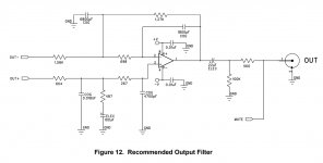
I'm looking at the output filter recommended in the datasheet and I notice it's the same two pole type of filter recommended in the AK4396 datasheet. There's a few differences, apart from part values, the CS4398 circuit has two caps to ground instead of one between the outputs and there's an extra 100uF cap in series to ground with one of the resistors. What does the 100uF cap do in this case? I simulated both and they perform very similar with 2.4k replaced with 2.7k (from the AK4396 datasheet). The AK4396 values are more BOM friendly. Any reason to go for the one in the CS4398 datasheet instead of the one from AK4396 datasheet?

For some reason in the simulation when I add the 2.5V offset to the one on the right it doesn't work right.
Also another curiosity is the high DC blocking cap value, at 22uF. For 100k it would work pretty ok with 2.2uF, maybe 3.3uF. At 2.2uF you'd loose 0.13dB at 20Hz. I think that's absolutely fine considering that would allow for other types of caps not just electrolytic.
Assuming you are talking about the output filter attached below, the output filter design is not symmetrical relative to the inverting and noninverting dac analog outputs. The 100uf cap appears to be a DC blocking cap to prevent voltage divider attenuation of the DC offset present on that dac output. Rather, they want the DC offsets on both dac outputs to stay the same.
Attachments
Last edited:
Rather, they want the DC offsets on both dac outputs to stay the same.
Why would that be better? There's still a DC blocking cap at the output, and the AK4396 version has 2.5V on the output.
I also can't make the CS4398 version to play nice. I get 12VDC offset on the input of the opamp with 2.5V offset in the source.
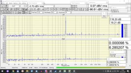
Also there's a mistake in the AK4396 values I posted, a 2.7k resistor should be 150R. The AK4396 is a bit worse in higher frequency attenuation but still good enough:

You can combine the two caps to ground into a double value single one between them. The 100K is not required without the DC blocking cap, I think. The 560R is for the MUTE circuit. Without the mute circuit I think you can omit that as well. Maybe lower it to 100R for short circuit protection.
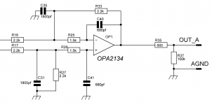
i'm use this schematic
Yes, that's right, you can do without 100k. Instead of 560 Ohms, you can install a T filter.
I used this scheme together with AK4493, the result is not bad.
This schematic will work well for the CS4398 but a few notes:
- There are better opamps than the OPA2134/2132 these days. Try OPA1611/2 series
- This circuit still presents an asymmetrical load to the DAC chip. In the case of the 4493 DAC, it doesn't appear to matter, if there was any ill effect from
the DAC's OP Cmos opamps you would likely see raised H2 and this is clearly not the case. Not sure what the 4398's OP driving capability is.
- The 560 ohm (R35) OP resistor can be a lot lower. Most opamps will happily drive a capacitive load with as little as 75 ohms on the OP.
You can also just strap a high level, HQ OP transformer straight on the DAC with no active electronics and get great results.
TCD
So then I think it's safe to use lower value output caps, somewhere around 2.2-3.3uF. The loss seems irrelevant with a 25k load. Maybe if your load is higher (lower impedance) then you'd need to check how much you're loosing at 20Hz with a 2.2uF cap.
Hi Trileru,
this Is what I am going to use for dual mono AK4493 dac
AK4493 DAC followed by AK4493 DAC to use only with balanced out
I can recommend you to see In practice If you need DC cap coupling output, If offset Is bellow 20 mV
this Is what I am going to use for dual mono AK4493 dac
AK4493 DAC followed by AK4493 DAC to use only with balanced out
I can recommend you to see In practice If you need DC cap coupling output, If offset Is bellow 20 mV
Last edited:
Why would that be better? There's still a DC blocking cap at the output, and the AK4396 version has 2.5V on the output.
I could take a guess at what they are up to, but experimenting might be the best way to find out. Maybe build a prototype and try it with and without the 100uf cap shorted. That's the only way to learn some things, especially some things that may not be obvious at first.
Last edited:
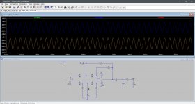
I can't even simulate it. LTspice acts strange with 2.5V offset in the CS4398 filter topology. Seems to work fine without the 2.5V offset, but the DAC output does have a 2.5V offset.
I attached the LTSpice sim, maybe someone has an idea on what's wrong?
I attached the LTSpice sim, maybe someone has an idea on what's wrong?
Attachments
Hi Trileru,
this Is what I am going to use for dual mono AK4493 dac
AK4493 DAC followed by AK4493 DAC to use only with balanced out
I can recommend you to see In practice If you need DC cap coupling output, If offset Is bellow 20 mV
Yes but AK4493 has no DC offset I think. CS4398 has a 2.5V offset.
How are you generating the offset voltage when it doesn't work?
I'm adding it to the source of the signal:

Could it be there's no DC reference for GND for the signal source? In the AK4396 version there's a resistor to ground, where here it's decoupled by the 100uF cap. I know LTSpice has issues with this sometimes.
Okay, I do see what looks like a problem. Probing both ends of the source generator, they are not equally at 2.5v above ground, and with equal and opposite AC potentials. The DC offset is not being interpreted in the way you seem to be intending.
In reality, there are two source generators both referenced to ground. They should have equal DC offset and opposite inversion AC components.
In reality, there are two source generators both referenced to ground. They should have equal DC offset and opposite inversion AC components.
Last edited:
Runs here. Not sure why you say it doesn't work.
Maybe because you didn't add the opamp?
Here's how it looks here:
Attachments
- Home
- Source & Line
- Digital Line Level
- CS4398 output filter