A friend of mine bought an amp in an exchange or similar a while back from a chap and then lent it to a friend as it was very low power, and not appropriate for his speakers at the time. Now he has horn speakers and got the amp back he's trying to understand the circuit and make sense of possibly improving it as it currently sounds...well a bit average.
Pictures attached, any idea how to sensibly deduce the circuit?
Neither me or my friend with the amp really have much of a clue to be honest!!
but very eager to learn 🙂
Pictures attached, any idea how to sensibly deduce the circuit?
Neither me or my friend with the amp really have much of a clue to be honest!!
but very eager to learn 🙂
Attachments
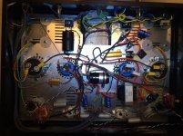
Obviously SS rectified B+. Obviously single ended and very roughly 3 WPC. I suspect triode wired 6AV5s, not genuine 6B4s.
I'm guessing cascaded 6SN7 section small signal circuitry.
I'm guessing cascaded 6SN7 section small signal circuitry.
I suspect triode wired 6AV5s, not genuine 6B4s.
I remember when those were selling on Ebay.
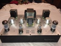
It's a nice looking build. Going to be a bit of work to convert it to real 6B4G's thou.
jeff
"Going to be a bit of work to convert it to real 6B4Gs thou."
. . . I agree.
Check the amp out completely before modification.
First modification needed, and most importantly:
A 6B4G DHT with 6.3VAC filaments, the ends of the filaments are 3.15VAC away from the virtual center of the filament.
That produces 120Hz intermodulation distortion on each and every musical tone, and the natural harmonics of that same tone (Or 100Hz in countries with 50Hz power mains).
Start with a trumpet playing 440Hz A. The trumpet puts out 440, 880, 1320, . . . Hz fundamental and harmonics.
440 + 120Hz, 440 - 120Hz; 880 + 120Hz, 880 - 120Hz; 1320 + 120Hz, 1320 - 120Hz . . .
It will take an additional filament transformer with 1 or 2 secondaries with a higher current rating (2 secondaries, if the 6B4G are self biased).
Then a DC filament supply for the DHT filaments (or 2 DC filament supplies for self biased DHTs).
That will get rid of the 120Hz/100Hz Intermodulation Distortion on the musical tones.
Check the amplifier out again . . .
Then any other issues of the amp can be taken care of.
6SN7 (or Russian/Chinese equivalents) cascaded, or 6SL7 SRPP. I do not know if the 6SL7s or (Russian/Chinese equivalents) ever had those rounded plates.
The amplifier looks good, and like it is well worth the trouble of modification. Can be a real jewel for a horn loaded loudspeaker, or for near-field listening with a small loudspeaker.
Last edited:
The tubes in the picture look like Sylvania / Philips ECG 6B4GA's. These were indeed 6AV5GA's internally triode strapped and wired to the 6B4G pinout. My testing in a Tubelab TSE board showed they did indeed work much like a real 6B4G and biased up close enough to work in many audio amps.
I can't quite make it out in the pictures, but if the plate wire from the OPT goes to pin 5 on the output tube the amp is wired for 6AV5 tubes and real 6B4G's can not be installed without modification. If the plate wire from the OPT goes to pin 3 on the output tube, the amp is wired for 6B4G tubes, and they should work, assuming proper hum balance circuitry is in place.
After a second look at the picture I see that this amp has 3 bridge rectifiers in it, and a pair of diodes that don't seem to be connected to anything, so the capability for DC heating is (or was) there. The two output tubes do seem to have their heaters wired in parallel and connected directly to a transformer winding. This indicates that someone has modified it and it may not be able to run 6B4G tubes without putting it back to its original state.
Last edited:
The colour bands on the resistors aren't very clear but I think I see 220k on the anode of the first triode section, directly coupled to the grid of the second as a cathode follower.
The high resistor value and round anodes suggest 6SL7?
The high resistor value and round anodes suggest 6SL7?
A second photo that is overexposed to blow out the highlights, but bring up the shadow areas, might allow me to see the details of the dark areas.
I do not know how Parafeed813 and Tubelab_com are able to see those shadow areas, but I may be almost as old as the sum of their ages.
I do not know how Parafeed813 and Tubelab_com are able to see those shadow areas, but I may be almost as old as the sum of their ages.
HollowState,
Much better!
Thanks!
I much preferred the old dark brown carbon comp resistor bodies with very distinguishable broad multicolor stripes around them.
Ohmmeters do not work on pictures very well.
That wiring looks much better than some of my amplifiers, which have been modified multiple times, with different output transformers; single ended; DHT and IDHT triodes; pentodes; beam power; triode wired; UL; LTP/CCS phase splitters, self inverting outputs with NPNs, LM317, and chokes; Parafeed, etc.
Don't ask about all the extra holes in the chassis.
I am in the process of totally unwiring one messy amp, all except the B+, and starting from scratch.
Hi everyone, I am Tonescouts buddy and owner of the amp in question.
Output valves are badged Sylvania 6B4G, drivers are badged Sovtek 6SL7.
There are smoothing networks for each individual output tube (seen next to valve bases on underside, but I am still checking heater supplies for 6SL7s.
Power supply looks to have been altered more than once and could do with a rebuild I think?
Still not sure what is going on with what looks like a choke in the middle of the top plate. There is another (completely different-looking) choke on the underside that might be for the other channel?
All early days so thanks for your advice. I only know what I've learned from years of tinkering (and the odd nasty shock! 🙂 so access to experts is confidence boosting.
I assumed SRPP referred to a push-pul circuit and this amp is definitely SE.
Am I missing something?
Please remember you are talking to a numpty...
Am I missing something?
Please remember you are talking to a numpty...
Is there a way to determine pin numbers from looking at the underside of the valve bases?
I can't see any numbers under there.
I can't see any numbers under there.
Is there a way to determine pin numbers from looking at the underside of the valve bases?
I can't see any numbers under there.
Octal tubes have a key. Start to the left of the key and count clockwise.
A second photo that is overexposed to blow out the highlights, but bring up the shadow areas, might allow me to see the details of the dark areas.
I do not know how Parafeed813 and Tubelab_com are able to see those shadow areas, but I may be almost as old as the sum of their ages.
I'm 68, so Parafeed813 must be really young or you're pretty old. I did cheat a bit by using a 44 inch 4K TV screen to see the small stuff. Details in the corners were still just guesses though.
Even in the original picture the twisted black wires from the power transformer can be followed to the left most end of a terminal strip. From there a white and black twisted pair go to the left output tube. A red black twisted pair go to a tape splice where they turn into a white and black pair going to the right output tube. The lightened picture reveals them to be pins 2 and 7 confirming that to be the filament circuit.
The original picture shows a bridge rectifier connected to the blue wires from the power transformer. It has a large cap across it's output, so I assumed it's a DC supply for the input tubes, but I didn't chase down the wires.
There is a larger square bridge on the other side of the power transformer. I can't tell if it's even connected to anything.
Just below that are 6 diodes on a terminal strip. Two are not connected, the other form a bridge. From the original photo I could deduce that it is the B+ bridge since the negative end goes to the ground bus running between the two blue caps. The new picture shows a green wire from the power transformer feeding one leg. The other leg is fed by a red wire coming from a tape splice, making it unclear as to what it's connected to. The matching green wire appears to be taped up, so it's possible that only half of the secondary is being used.
It appears that there is a CRC filter (R being the large gold one) feeding into two chokes. The choke under the chassis feeds the driver tubes via the brown resistor in the cable clamp and the two white resistors and the blue caps, which each feed their respective channels. The choke on the top feeds the output transformers via the black cap, the small gold resistors, and the silver caps.
The new picture also confirms that each output tube has it's own cathode bias resistor with three parallel bypass caps. The two cathodes are however shorted together by the filament circuitry. The plate terminal from the OPT is connected to pin 3 which is correct for 6B4G tubes.
Thanks Tubelab
Obviously I've still get my head round it as a whole, but your input has helped a lot.
It looks to me like there is an IC rectifier on one side (channel) but a discrete 4 diode rectifier for the other side? Is this likely to be an issue?
Am I to assume that the amp is wired for real 6B4Gs?
I would like to tidy up/upgrade the power supplies at some point, maybe on a dedicated board?
I see three rectifiers in the picture. The one on the left is the heater supply for both of the 6SL7's (both channels).
Both channels use the same AC heater supply for the output tubes. This is fine for the tubes that you currently have, but will create hum with real DHT 6B4's.
The discrete diodes are the B+ supply for both channels.
I can not tell what's connected to the square bridge rectifier mounted near the diodes.
The packaged bridge rectifiers are not really IC's. They have 4 individual diodes in one package to make mounting and wiring easier.
Tubelab,
Happy Next Birthday, both to you, and to Parafeed813 in advance.
You got me . . . 75 - 68 = 7, means Parafeed813 has to be only 7 years old.
He would have to be a child prodogy!
And Parafeed813 would have had to join diyAudio 1 year before he was born!
In any case, I can hardly wait until Barrymidd's amp is running with 6B4G tubes.
I want to "hear" how it "sounds".
Last edited:
- Home
- Amplifiers
- Tubes / Valves
- 6b4g amp mystery