At low frequencies a cone moves as a whole. This is the 'pistonic' area of operation. At higher frequencies the cone starts to flex, leading to resonances. This is what is referred to as 'breakup'.
These resonances are at fixed frequencies and are thus not harmonically related to the input signal. Non-harmonic distortions like this sound bad, and so should be avoided like the plague.
Breakup behaviour depends on cone material and geometry. Paper has very well damped breakup modes, which is one reason why it's such a commonly used material. More rigid materials, like metal, have very bad breakup modes, but fortunately they tend to be higher in frequency and so can be avoided with care.
There are ways to control breakup modes by treating the cone with various coatings.

Ok..
How do we get the breakup modes of a particular speaker, is there any particular software, testing method for it.
How do we get the breakup modes of a particular speaker, is there any particular software, testing method for it.
Stiffer cones better?
Its rather more complex than that. All cones breakup, in fact manufactures like Jorden build this in to their cones to get wider frequency response. So there is "bad" break-up and "good" breakup.
"Bad" breakup is where strong resonance is triggered which produces an output is not necessarily related to the sound desired.
As above, paper has good internal damping so it is easier to control resonances, and acheive a smooth sound over a reasonably wide frequency range. For these crossovers can be simpler. In general rigid materials produce resonances at higher frequencies than softer materials, but much worse in magnitude, such as the Seas metal cones. For these more complex crossovers are needed, to limit their ouput to the pistonic range.
However breakup can be controlled using rigid materials as well. as Jorden has shown. He manages to make his cones pistonic at low frequencies, but flex in a smoothly controlled manner to effectively reduce cone area at higher frequencies, producing a wide frequency range. (This is very much simplified, so please don"t jump on me- go read his book).
Opinions on cone material are just that, much depends on the designer and the intended purpose. So you cannot simply say sofy bad, hard good.
I am not aware of any software that measures breakup. An experienced person can see indications in the freqence response and impedence curves that will cause him to suspect breakup. There are a number of good speaker designers on the net that discuss this in relation to their enclosure and crossover designs
KEF did a lot of work using visual interference patterns and lasers that if you are interested is worth reading. B&W have also done more since. Not really for the DIYer.
crissty said:Ok..
How do we get the breakup modes of a particular speaker, is there any particular software, testing method for it.
You can model the breakup of a cone with FEA, but this will only be as accurate as your material properties are, among other things. This kind of tool isn't available to most people anyway.
If the speaker has undamped breakup modes (ie, with large amplitude), you can run the speaker under a stroboscope and watch the cone surface move.
Or you can whip out your laser vibrometer and measure the velocity of the cone surface at a bunch of different points to generate a map of the cone. There's an AES preprint showing this on the JBL Pro website. It's 'High frequency components for high output articulated line arrays' by Doug Button if you're interested. See p.27.
I forgot to mention that waterfall curves are useful in identifying major resonances.
For a DIYer these are probably the easiest and simplest tool to identify the frequency, but not the location of the resonance. With experience you can make an intelligent guess, and hence trial a possible solution.
MarkMcK has posted a lot of information in this forum about improving small TB drivers, either with glue rings or physical distortions which is worth reading.
VAF is an Australian manufacturer that damps some cone resonances with felt pads, (which also add mass as well).
In a plain vanila frequency response chart, damped breakups usually manifest themselfs as a series of horizontal S type smallish ripples. In a metal cone you get a hard peak or a twin peaks instead. Its always there where you see long tails on the related waterfall.
Old threat, new to speaker design.
I read on the forums discussion of designers talking about an specific driver and a popular expression is " you need to work breakups on the crossover", or "these metal diver have breakups that needed to be tamed" all shown with a level of mystery and lack of detail that make me feel like an outsider on the taming club.
So, can any show a simple example of a driver, and how to "tame" the breakups. Really, it is running me mad with designer paralysis. I want to use for my first two way design a metal driver, the Anarchy 6.5 and the metal taming fear is making me consider a paper cone, with softer breakups.
tks in advance.
The main thing to do is to make sure the crossover cuts off the breakup region.
Some try to navigate the resonances using filters, with varying degrees of success because not all breakup is fixable with a crossover. Besides, if you go too high your cone will become directional. They are best kept within a certain range.
Some try to navigate the resonances using filters, with varying degrees of success because not all breakup is fixable with a crossover. Besides, if you go too high your cone will become directional. They are best kept within a certain range.
And pick nice smooth responses without peaks.
I’ve been itching to do something with eminence delta pro 12a
I’ve been itching to do something with eminence delta pro 12a
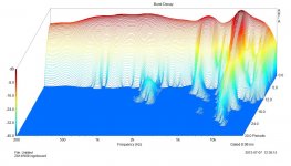
How about some pics from the cellar. I dusted them off carefully. Subject: the ZA14 an otherwise very nice metal cone which has a nasty breakup mode at 9kHz. Measurement: periodic pink noise on ARTA, close range mic. Plot: Burst decay, which essentially shows any resonance.
The first plot clearly shows the resonance at 9k. Not only in amplitude but also in time: like a bell, the cone produces sound quite long after the electric signal is gone. After 24 periods, which actually is 2ms, the decay level is down 32dB. Anyone care for a discussion about if one could hear the delayed sound?
Mind you, other effects (1,7k, standing wave in the cabinet, and a diffraction effect from the cone edge at around 4k) are visible too.
The second plot shows the effect of the applied filter. 3d order lowpass and a sinkhole on 9k. Back then I used a cap and a resistor parallel to the series coil.
The 'ringing' due to the coil and cap above 9k, combined with the resonance itself is down some 40dB. And since my ears aren't that sensitive, this is perfectly OK.
Conclusion: resonances in metal cones can be treated. But only way out the passband. I'd say your average lowpass frequency should be 1/3 of the resonance frequency to be perfectly sure.
Attachments

Hi Mark
Can you also measure THD ? You did correctly mention the 1/3 of the resonance rule for the crossover (or better even lower). This is due to the harmonic distortion of the motor that can also trigger those breakup resonances.
Regards
Charles
Can you also measure THD ? You did correctly mention the 1/3 of the resonance rule for the crossover (or better even lower). This is due to the harmonic distortion of the motor that can also trigger those breakup resonances.
Regards
Charles
Last edited:
Hopefully individual distortion levels rather than THD / a lumped total.
1/3 isn't a rule as such, although it can certainly serve as a useful ROT / guideline -depends how steep your XO slope is, where & the quality of the motor design.
1/3 isn't a rule as such, although it can certainly serve as a useful ROT / guideline -depends how steep your XO slope is, where & the quality of the motor design.
Last edited:
I would even go as low as 1/5 or less depending on the severity of the breakup. The H5 is oftentimes horrid due to the breakup (see W22EX as an example) and that cannot be tamed by notching the peak.Hopefully individual distortion levels rather than THD / a lumped total.
1/3 isn't a rule as such, although it can certainly serve as a useful ROT / guideline -depends how steep your XO slope is, where & the quality of the motor design.
Alternately, the driver could be acoustically shaded with felt (higher attenuation with increasing frequency) or used side-firing as the peak would typically be extremely attenuated 90 degrees off-axis, i.e. driver beaming helps reduce the audibility of the breakup in that situation
I would even go as low as 1/5 or less depending on the severity of the breakup. The H5 is oftentimes horrid due to the breakup (see W22EX as an example) and that cannot be tamed by notching the peak.
Ouch, 18dB rise @ 1KHz from the primary bell-mode. That'd melt your ears. 😉
I haven't worked with the W22 but from the HFC measures it starts to get in trouble at about 2KHz (you can see the glitch in the impedance indicating a resonance issue / energy storage), which from my perspective would realistically rule out an XO higher than, say, 1.4KHz with a minimum of LR4 slopes for that reason alone. Still, assuming for sake of example that wasn't there & ignoring potential issues with the polars for a moment, you could probably get away with, say, 1.8KHz or (with fingers crossed) about 2KHz if you stamp on the driver hard enough -LR6 or LR8 acoustic, probably with notched / Chebyshev type II filters to avoid excessive component numbers / losses. That should shunt it sufficiently low to avoid excess HD amplification.
If the low-pass is around 700 Hz or higher, you will start to see amplification of HD5. No clue whether the driver has significant HD6/HD7/..., but if it did, you might want to cross even lower. Such a shame; the W22EX could still be a world-class driver if all they did was stamp in a few stiffening ribs a la SB65WBAC25 to push up the breakup a bit more so that you could wholeheartedly use the driver for what its size would typically prescribe. Or add a bit of damping and live with a slight loss in sensitivity... a very advantageous compromise IMO.Ouch, 18dB rise @ 1KHz from the primary bell-mode. That'd melt your ears. 😉
I haven't worked with the W22 but from the HFC measures it starts to get in trouble at about 2KHz (you can see the glitch in the impedance indicating a resonance issue / energy storage), which from my perspective would realistically rule out an XO higher than, say, 1.4KHz with a minimum of LR4 slopes for that reason alone. Still, assuming for sake of example that wasn't there & ignoring potential issues with the polars for a moment, you could probably get away with, say, 1.8KHz or (with fingers crossed) about 2KHz if you stamp on the driver hard enough -LR6 or LR8 acoustic, probably with notched / Chebyshev type II filters to avoid excessive component numbers / losses. That should shunt it sufficiently low to avoid excess HD amplification.
SEAS W22EX001 | HiFiCompass
To this day, no one has shown rigorously the audibility of the various spectra, at what "music" level, and the effect of masking in different situations, but it certainly does not give me the warm and fuzzies to see H5 at 0.1% all by itself (at only 2.83 V drive level, no less).
EDIT: Then again, if used as the bottom of a relatively-compact 3-way, it's fine as is. Tweeter down to ~2-2.5 kHz, mid down to ~600 Hz, and the W22EX down to a sub (or full-range).
Last edited:
Do woven fiber cones still break up, or do they just do it in a smoother way? Also is break up the whole story, what about the ripple ( from the center of the cone ) " bouncing " from the edge and going back in?
- Home
- Loudspeakers
- Multi-Way
- cone breakup