Hi, as a method of learning, I was wondering if anyone with greater knowledge than myself could provide some feedback on this crossover design that I've been working on.
I've never designed or built a crossover before. Therefore I'm looking for pointers to understand if I'm on the right track (especially before purchasing components).
My main knowledge base for this design was the "Crossover Design Cookbook". To be fair its pretty much the same schematic, I'm just unsure if the application is working out the way it should.
So please let rip. It'll be useful to understand the good, the bad and the ugly.
🙂
Attachments
It's not too bad. Any concerns I have are offset by the uncertainty about your measurements. What can you say about those?
Are you using the Peerless 830657 and Dayton DC28F tweeter? And, as per post 2, are your graphs derived from measurements or manufacturer's specs?
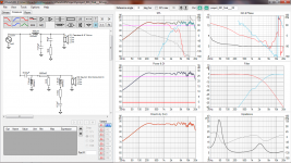
If these are your drivers, I'd want to put a small cap (0.33 mH m should do it) on the woofer inductor to get rid of the glitch at about 4,000Hz: when I've used that driver I found that works well. I did a test build of the 830657 and Vifa BC25TG based on a commercial design, it wasn't quite right but it sounded OK, I think it needed more work on phase issues but I don't have measuring equipment.
Also, your crossover point looks like about 2,500 Hz and I think you would want to have that at about 2,000 for the 830657. We'll need to know your baffle width, too please as the inductor value looks a little low unless these are going near a wall.
Geoff
Last edited:
The next thing to do would be to execute this design and perform measurements and the most important thing, listening evaluation.
Thank you @AllenB, @GeoffMillar and @Lojzek.
To answer your questions:
The graphs are derived from manufacturer's specs.
The woofer is a Peerless 850122 6.5" MID WOOFER CSX176H. Think its from early the 2000s and I picked it up cheap secondhand. And you're correct, the tweeter is a Dayton DC28F. The aim of the project is solely for learning purposes, so trying to keep costs low.
Correct. The Peerless 850122 has a frequency response of 38hz-5000hz. The Dayton 1300hz-20000hz. So I assumed 2500hz was safe. However, I think having it at 2500hz may be another factor behind the 4000hz glitch(?). I will try out the small-cap suggestion to see how it changes things.
I also thought having it X at 2000hz might be too close to the tweeters low-end. But Dayton seems to suggest you can have the tweeter work with a 1800hz xover. I just didn't trust that when the fr starts at 1300hz. Please tell me if I'm wrong or misunderstanding the manufacturer's frequency response specs.
At the moment I have no enclosure/cabinet design. My focus was on the crossover so I could buy the components, build the circuit using some alligator clips and see if/how it works out. Then I'd attempt some rudimentary measurements in some sort of baffle.
When I do get the enclosure/cabinet design, I'm keen to see if I can use a passive radiator to extent the Peerless 850122.
Thank you again for the replies, as @Lojzek suggests, I feel like I can proceed and buy the components and measure the outcome.
To answer your questions:
are your graphs derived from measurements or manufacturer's specs
The graphs are derived from manufacturer's specs.
Are you using the Peerless 830657 and Dayton DC28F tweeter
The woofer is a Peerless 850122 6.5" MID WOOFER CSX176H. Think its from early the 2000s and I picked it up cheap secondhand. And you're correct, the tweeter is a Dayton DC28F. The aim of the project is solely for learning purposes, so trying to keep costs low.
your crossover point looks like about 2,500 Hz
Correct. The Peerless 850122 has a frequency response of 38hz-5000hz. The Dayton 1300hz-20000hz. So I assumed 2500hz was safe. However, I think having it at 2500hz may be another factor behind the 4000hz glitch(?). I will try out the small-cap suggestion to see how it changes things.
I also thought having it X at 2000hz might be too close to the tweeters low-end. But Dayton seems to suggest you can have the tweeter work with a 1800hz xover. I just didn't trust that when the fr starts at 1300hz. Please tell me if I'm wrong or misunderstanding the manufacturer's frequency response specs.
We'll need to know your baffle width
At the moment I have no enclosure/cabinet design. My focus was on the crossover so I could buy the components, build the circuit using some alligator clips and see if/how it works out. Then I'd attempt some rudimentary measurements in some sort of baffle.
When I do get the enclosure/cabinet design, I'm keen to see if I can use a passive radiator to extent the Peerless 850122.
Thank you again for the replies, as @Lojzek suggests, I feel like I can proceed and buy the components and measure the outcome.
I have the 850122 in a 2 way with a Seas tweeter. If you are playing these in the open (i.e. not hard up against a wall / in a bookshelf) you will experience baffle step loss. You need to reduce the overall system sensitivity by 3 - 4dB - therefore you should be targeting ~ 84dB. As it stands - this speaker will be bass shy.
You can address this by beefing up the 0.9mH inductor. I recommend a value of between 2mH and 2.5mH to get the required shape.
I would also tame that breakup at 4Khz of the woofer. I think by doing the above and tweaking your parallel circuits on the woofer you can achieve this. I'll dig up my woofer filter and post here
Make sure you enter a positive Z offset for the woofer (acoustic centre is back from the tweeter assuming you are putting these on a flat, vertical baffle). I used 28mm.
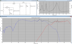
If you are targeting LR acoustic slopes (these sum to a flat on-axis response with -6dB at the crossover frequency (Fc)). You should be able to see a deep symmetric null at the XO point. Refer below.
PS: Ignore the peak at ~ 840Hz and the rise at the low end. This is an artefact of a nearfield splice I did.
Attachments
You need to know the baffle width before you sim the crossover, as that will help you work out the amount of Baffle Step Compensation as per Dave Bullet's post.
In terms of the crossover point, as a general rule, you want to cross a tweeter at a level which is at least double its 'resonant frequency' (Fs). With the DC28F, that's stated as 834Hz, so you want at least double that. However, if you do your research on that tweeter you will see that with a few exceptions, people like to cross it at around 2,000 Hz.
It can and has been be crossed lower in Curt Campbell's 'Tritrix' and Dennis Murphy's "Affordable Accuracy Monitor", so it can be done with careful crossover design.
I'm pretty sure that the wiggle in your sim at 4,000 Hz is a function of the woofer's response, at least, it is with the 830657. The small cap on the woofer kills that and makes for a cleaner sound.
I suggest using speaker grilles with the DC28F: it has a sticky dome which attracts fluff, dust and little fingers.
Geoff
Last edited:
Some people simulate the baffle step before they build a cabinet. This seems to work well, and it is a good way to go.
However I do not do this with 2-way designs. When I am in the planning stage, I just aim for a response that falls about 7 dB from 100 Hz to 1000 Hz. With a baffle width of between 7 inches and 11 inches, this is close enough for planning purposes.
In most 2-way designs, the baffle step compensation is achieved by extra inductance on the woofer.
When I have the cabinets complete, I measure the actual response and fine tune the filter network at that time.
I wanted you to be aware of all of your options.
I usually take the above baffle step average response of the woofer from manufacturer graphs (before any breakup peaks). This is usually > 600Hz on an IEC baffle. This figure usually matches the 2.83v sensitivity quoted on the spec sheet.
With the above - I then subtract about 4dB - to become my target response from 100Hz up.
With the above - I then subtract about 4dB - to become my target response from 100Hz up.
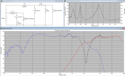
Geoff is right about the breakup. you can see the effect in my design - that tweeter and woofer do not sum correctly in the overall response @ 4KHz.
My intention was not a perfectionist crossover as I wanted a cheap refit for an existing design using on-hand passive XO parts.
Another parallel shunt following the 2nd order cap (smaller value cap cap and possibly shaping resistor) could be used to better match acoustic target.
My intention was not a perfectionist crossover as I wanted a cheap refit for an existing design using on-hand passive XO parts.
Another parallel shunt following the 2nd order cap (smaller value cap cap and possibly shaping resistor) could be used to better match acoustic target.
Some people simulate the baffle step before they build a cabinet. This seems to work well, and it is a good way to go.
However I do not do this with 2-way designs. When I am in the planning stage, I just aim for a response that falls about 7 dB from 100 Hz to 1000 Hz. With a baffle width of between 7 inches and 11 inches, this is close enough for planning purposes.
That's a great suggestion, I'd never thought of it that way
Geoff
Oh wow. More food for thought.
The small-cap did help reduce the 4000hz bump
Setting the 850122's Z to 28mm was also enlightening and I dropped the sensitivity of the system as suggested.
I need to spend some time considering the baffle. But I do like the approach of simulating it first.
Thank you for all the feedback. There's been a lot learnings taken from your comments.
Setting the 850122's Z to 28mm was also enlightening and I dropped the sensitivity of the system as suggested.
The above is very important - possibly moreso than bafflestep. Because you usually with your typical 6.5" / 1" - 2 way combo - target an Fc (crossover point) right in the very sensitive upper mid / lower treble range, where we are very sensitive to phase and resulting FR dips and peaks.
So many people sim without Z offset considerations.
Yes, and when you measure they are automatically included.. so Xsim has to be returned to zero to avoid doubling up 🙂So many people sim without Z offset considerations.
A word on the breakup. There is more happening than a ragged response. While it is possible to use a carefully crafted filter to make that smooth, this ignores off-axis behaviour. Better is to keep this region down past the crossover point.
Good point re measurement and Z offset. Let me caveat my advice.
You require a Z offset when either:
a) you are using manufacturer graphs with extracted minimum phase
b) you re-measure then (for whatever reason - say splicing a nearfield response) re-extract minimum phase
If you are using phase from a measurement and have not moved the mic between measurements across your drivers - then you would use a zero Z offset
Minimum phase can only be 'extracted' from an impulse response, and not from a frequency response plot. Once an impulse response has been 'flattened' into a frequency response plot, the information has been degraded, and proper phase information cannot be restored.
Allen - your advice confuses me... and I am probably about to demonstrate my ignorance here.
With a passive speaker design, my method of determining Z-offset is to measure the frequency response of the woofer, then the tweeter, then both together… import all three FRD curves into Xsim or Vituixcad and adjust the simulated delay until the simulated sum matches the measured sum.
So if your statement
I use a USB microphone... my understanding is that if I used a two channel sound card along with ARTA or REW I could directly measure the distance to each driver... but that is not what I use...
With a passive speaker design, my method of determining Z-offset is to measure the frequency response of the woofer, then the tweeter, then both together… import all three FRD curves into Xsim or Vituixcad and adjust the simulated delay until the simulated sum matches the measured sum.
So if your statement
is true, my method should not work... yes? or am I confused?Yes, and when you measure they are automatically included.. so Xsim has to be returned to zero to avoid doubling up
I use a USB microphone... my understanding is that if I used a two channel sound card along with ARTA or REW I could directly measure the distance to each driver... but that is not what I use...
Last edited:
It sounds as though you are aiming for a correct result, interesting method. What are your thoughts, eg. if you had phase measured from an appropriate distance, why would you be interested in the actual delay?
And just to be clear, I really do suspect I am slightly muddled on this point. I have never been 100% clear on what the difference is between "measured phase" and "derived phase" when using Xsim of Vituixcad... other than I know I need to be consistent between drivers.
I have read the definitions, but what I seem to be missing is what is the significance between "measured phase" and "derived phase"... Why would they sometimes be very similar and other times be very different, and when should I use one versus the other...
Active DSP is much easier (sigh)...
I have read the definitions, but what I seem to be missing is what is the significance between "measured phase" and "derived phase"... Why would they sometimes be very similar and other times be very different, and when should I use one versus the other...
Active DSP is much easier (sigh)...
- Home
- Loudspeakers
- Multi-Way
- Crossover Review