I concur. Just use as many LC (or RC) sections as you need to drop the end B+. I’d use at least 1 L.
dave
Or make a regulated supply if the voltage drop allows, it should be a must at least for screen grids g2. That will lift performance more than any tube rolling and transformer swap... 🙂
Found some time yesterday to do all calculations and draw the schematic.
Finished it this morning. 😀
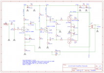
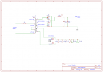
I think most information is on the schematic. I need to calculate 2 Power supply smoothing resistors still, but the rest is there. In the end I did go with a pentode output as this was in the original amp so did work with these OPT's
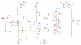
For the concertina phase splitter I went with a fixed bias to have the input stage decoupled from the concertina. So changes to the input stage wouldn't effect the bias of the concertina. What I'm not entirely sure about is the couple cap between the input stage and the concertina. I assumed the input impedance would be the parallel of both bias resistors (+-50k)
I hope I did not make to much mistakes 😕
Finished it this morning. 😀
I think most information is on the schematic. I need to calculate 2 Power supply smoothing resistors still, but the rest is there. In the end I did go with a pentode output as this was in the original amp so did work with these OPT's
For the concertina phase splitter I went with a fixed bias to have the input stage decoupled from the concertina. So changes to the input stage wouldn't effect the bias of the concertina. What I'm not entirely sure about is the couple cap between the input stage and the concertina. I assumed the input impedance would be the parallel of both bias resistors (+-50k)
I hope I did not make to much mistakes 😕
Attachments
Your power supply is choke input, also known as a swinging choke. There is a good thread here that goes into design considerations for those ...
Swinging Chokes
Did anyone mention damper diodes on here before? I was wondering if two damper diodes and two silicon diodes in a hybrid bridge could get the voltage output from your transformer into the correct ballpark, like in this thread ...
Hybrid bridge
You have the spare 6V winding, and damper diodes are 2 a penny.
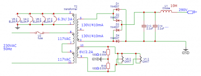
Look again at the power supply. Your circuit has 4 x EL84 so allowing 40mA each that's 160mA, plus a small amount for the 12AX7. Say 170mA total as a ballpark. So your choke needs to be specified for 200mA. 10 Henries is very good if you can find such a choke, but believe me, it will be big and probably not off the shelf. I would suggest something practical like a Hammond 159S which is 4H at 225mA.
Look at a tutorial on rectification in tube circuits. As drawn, this is choke input so you won't get anything like 290v out. For choke input you'll get a bit less than the AC secondary. So for 260v AC reckon on something like 245-250V DC. The idea of the small PSU caps like 2.2uf is to put them BEFORE the choke, not after, to raise the DC voltage as required. After the choke you need a proper large capacitor. I and others like to use polypropylene capacitors, the most easily available being "motor run" capacitors (NOT motor start). 47uF is a good size, and you can use more than one in parallel. Better is to use something like 47uF, dropper resistor, then another 47uF. If you have a stock of motor run caps you can play around with the sizes.
You should model the power supply using software like PSUD, which is for a PC not a Mac. Download it and play around with it.
Damper diodes can be good in a hybrid bridge and run off 6.3v. I've used a couple of 6DT4 or 6AU4. But why not start with solid state rectification to make it simple and go from there. As always, allow for a bigger chassis than you imagine. Motor run caps are fairly large, though not expensive.
Last edited:
That is correct, and this makes it quite a tough load for 12AX7.What I'm not entirely sure about is the couple cap between the input stage and the concertina. I assumed the input impedance would be the parallel of both bias resistors (+-50k)
The usual resistors value for this application are in the megaohm range - for a reason.
Also:
1) 47k grid stoppers are too much for 12AX7 for hi-fi use (that's more of a guitar preamp value) - something in the 1-10k range would be more appropriate;
2) Never rely on the pot to act as a grid leak resistor - add another 470k-1M resistor from the pot wiper to the ground.
Andy, Thanks, I must have misread what you were trying to say. I'll change that
TG, I was not sure about the load for the !@AX7 either, but did not immediatly find an equivalent cirquit. I've read that the grid current will be somewhere in the range of 10uA. That would make sense if you say that these will need to be larger. 1.8meg and 680k would that be ok?
For the grid stoppers, 4.7k would be fine than? I'll add a 470k grid leak resistor to the input of the 12AX7
Make sure all your capacitors are properly rated for voltage before buying any. If you use motor run polypropylene caps they're often 450v AC rated which is good. With no load your output voltage will be something like 370-380v DC. So use 500v DC parts or preferably 630v. 450v AC corresponds in theory to 1.4x DC rating, so something like 630v DC. Same for all the caps in your circuit. They all need to be over-rated.
A choke I/P filter yields approx. 0.9X the AC RMS value, less losses. 234 V. before losses will not get things done. 🙁 A cap. I/P filter yields approx. (21/2)(AC RMS value), less losses. 367.7 V., before losses, is something to work with.  Use CLCRC filtration to get the desired B+ rail voltage. Use an amount of capacitance in the 1st position sufficient to keep the rail voltage up and no more. The bulk of the energy storage goes into the final reservoir part.
Inductors employed in choke I/P service have to be rated for that duty. They are subjected to high stresses. An off the shelf Hammond or Triad part needs to be substantially derated, if used in choke I/P service.
Inductive kick back spikes are a fact of life, when choke I/P filtration is employed. Said spikes will destroy SS diodes. A protective 0.01 μF. cap. whose WVDC is as large as can be obtained is placed "across" the rail and that makes the filter cLC. The protective part does not impact on choke I/P behavior.
You will be very hard pressed to find a more cost effective choke for the PSU filter than the 200 mA. rated Triad C-14X.
1N4007 diodes generate lots of switching noise. UF4007s are much quieter and not particularly expensive.
Given its high plate resistance (RP) and low transconductance (gm), the 'X7 triode makes a wretched "concertina" phase splitter. Use a 'X7 section voltage amplifier and 'U7 section "concertina" phase splitter.
If you are going to filter infrasonic noise at the amp's I/P, as (IMO) you should, place F3 in the 16-18 Hz. range. The object of the exercise is to prevent O/P "iron" core saturation due to a large LF error correction signal that's GNFB induced.
Use CLCRC filtration to get the desired B+ rail voltage. Use an amount of capacitance in the 1st position sufficient to keep the rail voltage up and no more. The bulk of the energy storage goes into the final reservoir part.Inductors employed in choke I/P service have to be rated for that duty. They are subjected to high stresses. An off the shelf Hammond or Triad part needs to be substantially derated, if used in choke I/P service.
Inductive kick back spikes are a fact of life, when choke I/P filtration is employed. Said spikes will destroy SS diodes. A protective 0.01 μF. cap. whose WVDC is as large as can be obtained is placed "across" the rail and that makes the filter cLC. The protective part does not impact on choke I/P behavior.
You will be very hard pressed to find a more cost effective choke for the PSU filter than the 200 mA. rated Triad C-14X.
1N4007 diodes generate lots of switching noise. UF4007s are much quieter and not particularly expensive.
Given its high plate resistance (RP) and low transconductance (gm), the 'X7 triode makes a wretched "concertina" phase splitter. Use a 'X7 section voltage amplifier and 'U7 section "concertina" phase splitter.
If you are going to filter infrasonic noise at the amp's I/P, as (IMO) you should, place F3 in the 16-18 Hz. range. The object of the exercise is to prevent O/P "iron" core saturation due to a large LF error correction signal that's GNFB induced.
Wise words from Eli as always. Since you want around 300v DC out of your PSU it won't be choke input, and the size of the first cap will help you determine the output voltage.
The Triad choke is nice - 6H at 200v. That's a US part, however and I know from experience that shipping and customs add substantially to the cost in Europe. That's why I suggested the Hammond 159S at 4H and 225mA since Hammond has a good dealer network in Europe and this keeps the cost down. In fact the 159R is 6H and 200mA like the triode and costs €22. You can see the range here. BTB is a good supplier for tube circuits in Europe - good stock and prices.
https://btb-elektronik.de/suche/?searchterm=choke&searchform=Submit
The Triad choke is nice - 6H at 200v. That's a US part, however and I know from experience that shipping and customs add substantially to the cost in Europe.
I've had a few Triad chokes from Digikey, and as long as the total order is up around 40 quid, shipping is free.
In the UK we get customs and handling charges on top of shipping, alas. My last Digikey order for £40 had almost that in extra charges. I source all my parts in Europe.

Good work - I think you just forgot the reservoir capacitor after the choke in the PSU. Is anyone else using motor run capacitors? I use these kind of caps.
Universal Microfarad Start Run Motor Capacitors MFD 1.5UF - 80UF Spade Capacitor | eBay
Universal Microfarad Start Run Motor Capacitors MFD 1.5UF - 80UF Spade Capacitor | eBay
I also use cheap motor run capacitors, usually from surplus, whereas not in the PSU's, but in my xover networks. No need for non polarized capacitors if a standard electrolytic also fulfills the task sufficiently.
Best regards!
Best regards!
I'm completely with you. It appears to be one of his immanent deficiencies.My apologies for the somewhat harsh language @Schmitz77, but you clearly haven't read or understood the complete topic. And judging, from all your answers on this post, you're clearly not interested in what I'm after.
Best regards!
@Ketje
Big thanks,
Any chance you can explain why you changed these items, so I can understand. For example the fixed bias of the concertina has changed to self bias, but I'm not exactly sure why.
Again many thanks.
Jona
Big thanks,
Any chance you can explain why you changed these items, so I can understand. For example the fixed bias of the concertina has changed to self bias, but I'm not exactly sure why.
Again many thanks.
Jona
I'm not Ketje, but I would have also suggested a self biasing Concertina. Self bias is the usual way to go with small signal stages, and in a Concertina the grid leak resistor is bootstrapped for a large input impedance (hence the 22 nF coupling capacitor).
Best regards!
Best regards!
- Home
- Amplifiers
- Tubes / Valves
- EL84 tube amp build, how to start?