One could always make it MCU-compatible: isolation amplifiers are available for as little as 5$ or even less nowadays.
Another option would be a small slave controller on the high side to carry out A/D and D/A conversion in serial format, linked to the main controller via cheap digital optocouplers.
Another option would be a small slave controller on the high side to carry out A/D and D/A conversion in serial format, linked to the main controller via cheap digital optocouplers.
Here is a small (but important) revision of the main section.
I noticed that during power-up and down, the output voltage became uncontrolled.
As it could damage sensitive circuits, it was necessary to fix it.
The cure is the addition of a resistor R45 of 1K8 in parallel with the diodes supplying the reference for the CCS biasing the output ballast:
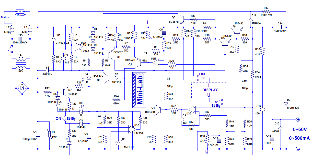
This forces the ballast to shutdown earlier than the rest of the circuit, thus muting the output when the non-regulated voltage is too low
I noticed that during power-up and down, the output voltage became uncontrolled.
As it could damage sensitive circuits, it was necessary to fix it.
The cure is the addition of a resistor R45 of 1K8 in parallel with the diodes supplying the reference for the CCS biasing the output ballast:
This forces the ballast to shutdown earlier than the rest of the circuit, thus muting the output when the non-regulated voltage is too low
Attachments

Thanks for publishing your lab supply Elvee!
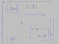
In an effort to understand the circuit I spent some time re-arranging the pieces. I hope I didn't break it! 😱
I don't fully understand it yet, but I am getting there 😀
In an effort to understand the circuit I spent some time re-arranging the pieces. I hope I didn't break it! 😱
I don't fully understand it yet, but I am getting there 😀
Attachments

At first sight, it looks a bit strange, but allow me some more time for an in-depth check....I spent some time re-arranging the pieces. I hope I didn't break it! 😱
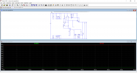
OK, it took some time but I managed to review your schematic: mine was too cramped, because I wanted everything to be easily legible at a glance, but yours is somewhat ...aerated, which isn't easy either.
The sim is "repaired", the problem was simply the use of a LT1055 in the voltage controller: its common mode doesn't include the V- rail.
Instead, you should use the other half of the LT1013, as I did:
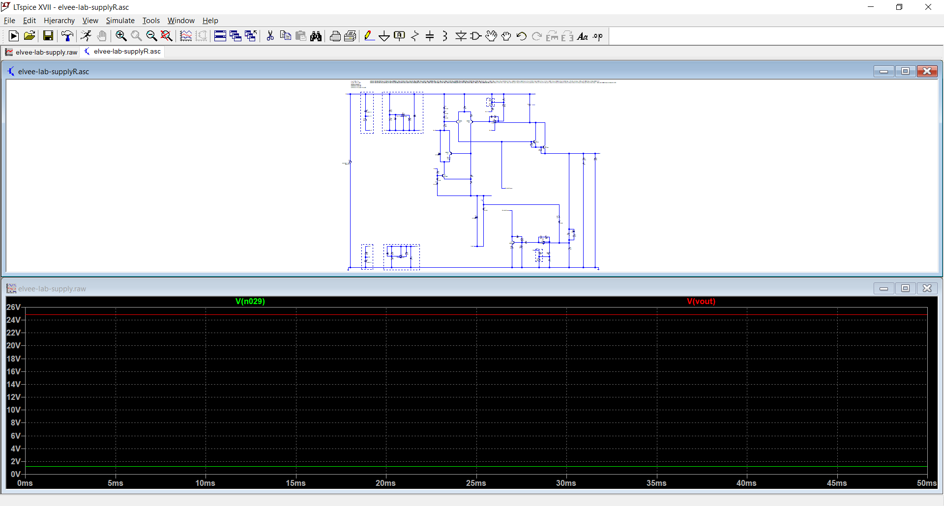
Note that the parts of the circuit you have omitted play a non-negligible role in practice, and should be included in a real build, even if the sim appears to work without them
The sim is "repaired", the problem was simply the use of a LT1055 in the voltage controller: its common mode doesn't include the V- rail.
Instead, you should use the other half of the LT1013, as I did:
Note that the parts of the circuit you have omitted play a non-negligible role in practice, and should be included in a real build, even if the sim appears to work without them