Since this is your first build,,,
My advise don't bite off more than you can chew- As such- schematic you posted #8 isn't where you should begin. There are plenty of much easier PP EL84/6BQ5 that can be built to start from that will pique your interest.
This^^
IMO- the best 6BQ5 / triode driver design that I've listened to. Bottom line is keep melting solder;<)
Jim
My advise don't bite off more than you can chew- As such- schematic you posted #8 isn't where you should begin. There are plenty of much easier PP EL84/6BQ5 that can be built to start from that will pique your interest.
But the amp that I really fell in love with many years ago was a Dynaco St-35, which uses el84's. Smallish and simple amp, and you can find many kits and schematics. It's got a certain magic to it. You can also look into Tubelab on this forum which is a fantastic resource with a great community. Both PP and SE designs are available there
This^^
IMO- the best 6BQ5 / triode driver design that I've listened to. Bottom line is keep melting solder;<)
Jim
Last edited:
If your OPTs are truly 6.6K then you need to decide whether to get new 8K OPTs for EL84s or use a tube more like EL34. I imagine it's cheaper to keep the OPTs. I'm assuming that 6.6K is a little low for an EL84.
the 6,6k OPT is what came with the amp I disassembled which used EL84 tubes. I'd like to keep the OPTs if possible as new ones will be somewhat more expensive. I'd like to keep the cost down a bit for this one, just to see if I get the hang of it.
I found this schematic online that references EL84 tubes in stead of 6v6 tubes and uses the same PP approach as the original amplifier. Would this work by just swapping out the 6V6 tubes with EL84's?
The only issue I currently see is that the output voltage of my power TF is a little higher than 238VAC mine is at 260VAC. would that pose a problem?
Attachments
Last edited:
Your mains transformer isn't a problem - you can use the size of the first capacitor to determine the output voltage. For 260AC you'd get say 230-240v with no cap and choke input (you have a choke?), after which you go up something like 2uF, 4uF, 6uF, 8uF and the output voltage will rise accordingly up to maybe 300v. You are using tube rectification or solid state?
Your operating point will be more like 250v, 34mA, -9v in triode which is what Mullard suggests. However the Ri is 2K which is a bit high for a 6.6K PP OPT. Mullard suggests 10K. Have a look through the data.
https://frank.pocnet.net/sheets/129/e/EL84.pdf
The data shows that a 6.6K OPT is suitable for UL (ultra linear) operation but for that your OPT would have to have UL taps, i.e. there would be 5 wires/lugs on the primary not 3.
Last edited:
Ok so if I understand correctly: If I want to keep the OPT's I need to go to other tubes e.g. EL34. Or if I want to keep the tubes, I need to go for different OPT's
I think i will go for option 1, keep the OPT's and change the tubes as I don't really know if the output tubes all work. The transformers are functional.
Would the schematic I posted in #23 be adaptable to EL34 tubes then? as it seem feasible.
can someone point me into a direction where I can find an explanation on the calculations for these PP amplifiers without distributed load. I'd like to do the math 😀
PS: This might be a silly question, but what trickery did the designers of this H-52 amp use to make the EL84's work in PP with this 6.6k OPT?
thanks
never mind the question about the calculations: I've found a link to VTADIY: Vacuum Tube Amplifiers DIY - Vacuum Tube Amplifiers - DIY also thanks to @andyjevans.
It seems that the calculations are far more similar to the calculations for a transistor amplifier than I expected. 😀
I'll read that book and then I'll see what I can come up with.
Thanks to everyone for the provided answers.
It seems that the calculations are far more similar to the calculations for a transistor amplifier than I expected. 😀
I'll read that book and then I'll see what I can come up with.
Thanks to everyone for the provided answers.
There's nothing wrong with 6.6k OPT for a pair of EL84. It might be not perfect, but it's more than acceptable.
260VAC on the PT will give you 330-350VDC depending on the capacitors value and the choke's DCR (actually you can deliberately use cheaper high DCR choke to drop the B+). Avoid choke input filtering - you'll need pretty special choke for that, "general use" ones won't do. The PSU in the post #23 is kinda OK, but go for 450V capacitors for your PT.
Pentode-configured output stage without some sort of NFB isn't good for most modern speakers, and adding the NFB correctly requires some knowledge and equipment. I'd suggest going for the triode mode for the EL84. One good example of the triode-strapped EL84 PP output stage is the John Broskie's amp, though I'd personally would go for individual EL84 biasing and slightly higher quiescent current (680..750R+100uf for the each cathode instead of those 400R+1000uf common ones). You can actually use 12AT7 instead of 6N1P for this particular design and still get good results.
Attachments
How sensitive are the speakers you intend to use, and how loud do you listen, and what size room? If you have sensitive speakers and a small room and don't listen loud, then operating an EL34 in triode PP should be a nice sound. Makes the design simpler since there's no pentode circuit and no overall feedback loop. Here for instance
Schematics The Allen Wright PP-1C
You need some reading here to understand all this. All the data can be found at Frank's tube site.
There's a loadline site here where you can look at different operating points for common tubes.
Universal loadline calculator for vacuum tubes - Vacuum Tube Amplifiers - DIY
I have a pair of B&W 686 s2 speaker I intend to use for this amp
their sensitivity rating is as follows: (84)85dB spl (2.83V, 1m)
Room to listen in is my living room, about 50 sq meters
definitely no loud listening. Just regular volume to enjoy the guitar music of Dire Straits and the like.
As I don't really know what to expect from an amp like this. I'm not really sure about what direction I need to go. So My thought was: Build one, see if I like it and then build a better one and invest in proper components 😀
does that seem reasonable?
Probably full-pentode with GNFB then.
You can build pentode ST-35 variant indeed using half of the 12AX7 as the first stage and the half of the 12AU7 as the second one instead of those 7247s.
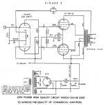
Or maybe something like below (also in full pentode).
In both cases oscilloscope (the borrowed one) might be needed to adjust the GNFB cap value for the optimal performance.
You can build pentode ST-35 variant indeed using half of the 12AX7 as the first stage and the half of the 12AU7 as the second one instead of those 7247s.
Or maybe something like below (also in full pentode).
In both cases oscilloscope (the borrowed one) might be needed to adjust the GNFB cap value for the optimal performance.
Attachments
No, need some (little) changes.And the input sensivity goes up.I found this schematic online that references EL84 tubes in stead of 6v6 tubes and uses the same PP approach as the original amplifier. Would this work by just swapping out the 6V6 tubes with EL84's?
Mona
Attachments

Do you have the old chassis for that HFE stereo radio for which you have the schema?
If I was in your shoes, I think I'd start with that and the schema, then build the basic amp from the 12AX7 onwards, and try it out. That would be a great learning experience in working point to point, and it is a straightforward circuit with a concertina phase splitter, so understanding what passives go where is 90% of the understanding.
You could even start after the 12AX7, since the gain should be plenty after that. And you can just try one channel.
The danger is that the OPTs will not deliver the sound quality you are expecting, and then you will never be sure if it was the operating point of the circuit you chose to build, or the hardware. It is a shame you did not get a chance to hear the amp before it was dismantled.
How big and how heavy are the OPTs?
PS Just checked it out on Radiomuseum, and they look like they should be decent quality! It was a nice piece of kit. I have a Pioneer from around that time, and I am hoping it will be rewarding to update it.
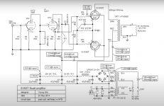
National SA52-H
If I was in your shoes, I think I'd start with that and the schema, then build the basic amp from the 12AX7 onwards, and try it out. That would be a great learning experience in working point to point, and it is a straightforward circuit with a concertina phase splitter, so understanding what passives go where is 90% of the understanding.
You could even start after the 12AX7, since the gain should be plenty after that. And you can just try one channel.
The danger is that the OPTs will not deliver the sound quality you are expecting, and then you will never be sure if it was the operating point of the circuit you chose to build, or the hardware. It is a shame you did not get a chance to hear the amp before it was dismantled.
How big and how heavy are the OPTs?
PS Just checked it out on Radiomuseum, and they look like they should be decent quality! It was a nice piece of kit. I have a Pioneer from around that time, and I am hoping it will be rewarding to update it.
National SA52-H
Last edited:
Probably full-pentode with GNFB then.
You can build pentode ST-35 variant indeed using half of the 12AX7 as the first stage and the half of the 12AU7 as the second one instead of those 7247s.
Or maybe something like below (also in full pentode).
In both cases oscilloscope (the borrowed one) might be needed to adjust the GNFB cap value for the optimal performance.
Ok I think I'm getting it. Thanks
I do have an older analog 20MHz tektronix scope, but no dedicated signal generator. I'll either borrow one or quickly put something together.
I have some experience of PP EL84 amps, since I have a Leak Stereo 20 which I've continually upgraded over the years. Personally I hated the global feedback and much preferred it in triode without any feedback. Unfortunately I should think you really need some more output than triode EL84s give you.
That's the reason that if it were me I'd use a pair of EL34 in triode. I'm guessing you'd have just enough output for your speakers since the EL34 in triode can give you up to 25W anode dissipation, while the EL84 will only go up to 12W. This is anode dissipation, not watts output. The formula is a-k voltage (anode to cathode) x current in amps. So 12W would be for instance 300v x 40mA (.04A).
If your mains transformer gives you say 320v DC then if you used the EL34 at 20W dissipation it would be something like 300v a-k at 65mA. But this then raises the question of whether you could put 130mA (plus input tubes) through the mains transformer where it would have been more like 80mA before (plus input tubes) for 2 x EL84 in pentode.
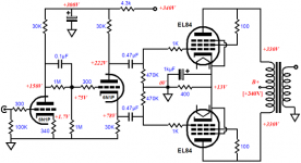
So with the iron you have I guess it's safer to stick to an EL84 pentode design. The recommendations above for that are perfectly good. I'd add the "Bevois Valley" variation on the Leak Stereo 20 which you can find in Morgan Jones book "Valve Amplifiers". Operating point is 299v a-k, 40ma, -11v bias. Dissipation therefore right on 12W. This is ultralinear UL, however, so you'd have to adapt it to pentode operation.
"bevois valley" in triode
That's the reason that if it were me I'd use a pair of EL34 in triode. I'm guessing you'd have just enough output for your speakers since the EL34 in triode can give you up to 25W anode dissipation, while the EL84 will only go up to 12W. This is anode dissipation, not watts output. The formula is a-k voltage (anode to cathode) x current in amps. So 12W would be for instance 300v x 40mA (.04A).
If your mains transformer gives you say 320v DC then if you used the EL34 at 20W dissipation it would be something like 300v a-k at 65mA. But this then raises the question of whether you could put 130mA (plus input tubes) through the mains transformer where it would have been more like 80mA before (plus input tubes) for 2 x EL84 in pentode.
So with the iron you have I guess it's safer to stick to an EL84 pentode design. The recommendations above for that are perfectly good. I'd add the "Bevois Valley" variation on the Leak Stereo 20 which you can find in Morgan Jones book "Valve Amplifiers". Operating point is 299v a-k, 40ma, -11v bias. Dissipation therefore right on 12W. This is ultralinear UL, however, so you'd have to adapt it to pentode operation.
"bevois valley" in triode
Last edited:
Hi Jona,
do I get you right that both output transformers are from the same unit that also had the EL84's? Then I'd re-use them in a PP amplifier with a pair of EL84's and a 12AX7, either as a voltage amplifier + Concertine phase splitter, or, what I'd prefer, a Schmitt/LTP PI. Apply sufficient NFB.
No need to buy other tubes, unless yours' are worn out.
And measure your OT's again with applying 6.22 Vac (or so) to the secondary. The result might be somewhat different - and more reliable.
Best regards!
Push Pull EL84s are a sweet sound ...
The EL84 triode Class A PP i am currently listening to is fantastic.
2 radios, 4 OPTs, 4 EL84s really points to all SE.
We did a series of evolutionary EL84 SE amps (7 iterations) and ended up with. variation on a scade feedback entode amp.
Note to OP: SE is always Class A (in hifi anyway). You can expect between 1.5 and 5 w depending on PS voltage and the details of the build.
dave
...ECL86...
Supposedly getting hard to get, and (ref Eli Dutmann) the 12AT7/ECC82 has a transfer curve such that when it precedes the EL84 the transfer curve of the 1st linearizes the final output transfer curve.
Adding the EL86 to the mix, and the radio scheme means 6 output tubes, and one of the amps PP. PP EL84 can be about 3.2w (our Class A PP) up to about 15w.
dave
To my mind the best 3 PP EL84 amps are EL Cheapo by Eli Duttmann (IIRC the amp started on another forum), Red Light District by SY, and Baby Huey by gingertube (evolved from Yves ECL84 amp)
Our EL84 triode Class A is based on the El Cheapo and uses a Scott LK48 as a base and transformers.
dave
Our EL84 triode Class A is based on the El Cheapo and uses a Scott LK48 as a base and transformers.
dave
Penthode operation without GNF gives troubles in the bass register (boink-boink). Turning to SE triode operation gives perhaps 2W/ch.
It depends.
GFB is not needed to reduce the output impedance, Scade feedback works well.
Pentode without any feedback is typically a current amp.
Any high output impedance amplifier wants to see a very flay speaker impedance curve (rare, bu tthey exist) or with an impedance curve that the convolution of part of the speaker impedance with the FR (measured with a voltage amp) tends to equalize/extend the FR. Some speakers (like the Fostex FExx6 series) what to see a high output impedance amplifier.
- Home
- Amplifiers
- Tubes / Valves
- EL84 tube amp build, how to start?