My son picked up a 1975 Fender Princeton Reverb Silverface at an auction.
It was pretty dirty/rusty, but when we plugged in it, it worked...briefly.
Now, though the pilot lite works, there is absolutely no sound, no hum, no nothing.
Is this a symptom of a bad transformer? They are really rusty.
I checked all the tubes (with a tube tester) and they appear to be good, and they glow when in the amp and powered up.
I used deoxit on all of the pots and tube sockets, as well as tried other speakers
Any advice on where I can begin troubleshooting?
 moved
movedWhat condition are the caps in?
Are you able to upload some pics of the amp internals?
What test equipment do you have available? Multimeter?
I think this one should be your schematic for a '75:

Are you able to upload some pics of the amp internals?
What test equipment do you have available? Multimeter?
I think this one should be your schematic for a '75:
Last edited:
The caps and everything else in the amp appear original, though nothing looks burnt or fried.
I have a multimeter, oscilloscope, heathkit tub tester available.
I've got both the layout and schematic diagrams.
I think my issue is understand how to test with both AC and DC current going on.
For instance on the layout diagram, it lists lots of voltages. If it was DC current I would simply place the red lead from the multimeter at the marked point, and the black lead on ground/chassis. Since it is AC current I don't understand where the Hot vs. Neutral is in the amp.
Here's the amp (the external speaker jack fell apart and needs replace, but I don't think it is causing any issues)
Thanks, I found that earlier and read it.
The high voltages do concern me, which is why I'm hoping maybe I can pinpoint the issue before either testing it powered up, and having to remove components and testing them individually.
The high voltages do concern me, which is why I'm hoping maybe I can pinpoint the issue before either testing it powered up, and having to remove components and testing them individually.
Links to the amp pics
1975 Fender Princeton Reverb - Album on Imgur
1975 Fender Princeton Reverb - Album on Imgur
1975 Fender Princeton Reverb - Album on Imgur
1975 Fender Princeton Reverb - Album on Imgur
Often those old blue caps go bad, as well as the big filter cap. I would personally replace all of those as a start.
My tip is to get some high voltage spring clip probes if you can. That way you can position them in the circuit and then switch on and off whilst remaining well away from the HV. Observe the voltage rating of any probe leads you use to ensure you don't get breakdown of the insulation.
And a non metallic stick (plastic chopstick for example) is good for poking wires and connections to find loose wires of bad joints.
... absolutely no sound, no hum, no nothing....
Put your son's ear IN the speaker. Absolutely NO sound?? No hum or buzz? Then it is the speaker jack, speaker, speaker transformer winding. Is there more than one jack? (uh, yes.)
My teacher, a half century ago, told me:
1. Check if you see any damage.
2. Connect a load to the amp. Use a lightbulb in series with the amps ac cord.
3. Measure voltages. Measure voltages. Measure.... Yes, more then once.
4. Then start thinking. Read the schematic and understand.
5. Redo 4 until you get it.
6. Then measure and do it again... Take notes, write it down, clear and nice.
7. Start at the Power Supply section.
8. Now you can check parts you think that can be bad. Think that CAN BE bad! If they are bad, replace.
9. Go to the Power Amp section. Repeat 8.
10. You must be able to hear something now, a faint his or the like.
11. Repeat 3 until 6.
12. Check the Preamp Section. Repeat 8, 3, 4, 5, 6.
And if you're uncertain, show the readings to the community, BEFORE buying any new part. We can help.
Be aware! High voltages on the power supply caps. Discharge them before putting your fingers in the amp. Keep one arm behind your back while the other is in the amp. Stay safe!
Thanks, I built a dim bulb tester today, and the amp test ok with the bulb.
I plan on sitting down tomorrow with a multimeter and start checking things
I plan on sitting down tomorrow with a multimeter and start checking things
Well I did some testing with the amp powered up.
Many voltages matched what was on the layout diagram, some were about half. (I'm guessing this is due to old caps and/or capacitors)
My real concern is that one one of the 6V6 tubes, it should read +410, but is reading -30. Any ideas what might be causing this?
layout with measured voltages


Many voltages matched what was on the layout diagram, some were about half. (I'm guessing this is due to old caps and/or capacitors)
My real concern is that one one of the 6V6 tubes, it should read +410, but is reading -30. Any ideas what might be causing this?
layout with measured voltages
Last edited:
Rusty transformers is NOT a for-sure problem (but hints at moisture trouble).
I bet your V2 is a 12AX7 not a 12AT7.
You probably have other wrong-part and tired-part problems.
-30V at 6V6 pin 5 IS correct. You cut-off where the grid resistors get fed from.
While you will get some sage advice here, you also have Hi-Fi folks who don't know the rough life a 1960s Fender has been through. There are several for-guitar-amp forums where this is all they do, and can tag-team you to clarity.
Attachments
Last edited:
Stanchfi,
do you hear someting throug the speaker?
Hum, noise, rumble... Anything?
The voltages looks ok.
I read that the speaker jack has fallen aprat.
If there is no sound, check the wiring of the jack. New or replacement.
Is you speaker ok?
Check the disconected speaker with a multimeter. It should show some resistance, between 3 and 6 ohms (average)
Or use a 9V battery and touch the terminals. Hear if the speaker makes a plopping sound.
Sorry for the delay in responding.
I got my son a re-capping kit for Christmas, and we attempted to install it yesterday.
Good news, it now makes sound, bad news it sounds like crap.
Here's a video of a Fender Rhodes being played through it
1975 princeton reverb - YouTube
Interestingly the re-cap kit came with 6 25/25 caps. but the amp itself only had 4
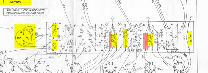
The missing caps are highlighted in red.
I don't think the amp ever had work done on it before from the looks of it.
Could it have been like this from the factory? (am I using the wrong schematics? AA1164 and/or B1270)
Is there any harm in adding the missing caps?
Again, any advice is appreciated
I got my son a re-capping kit for Christmas, and we attempted to install it yesterday.
Good news, it now makes sound, bad news it sounds like crap.
Here's a video of a Fender Rhodes being played through it
1975 princeton reverb - YouTube
Interestingly the re-cap kit came with 6 25/25 caps. but the amp itself only had 4
The missing caps are highlighted in red.
I don't think the amp ever had work done on it before from the looks of it.
Could it have been like this from the factory? (am I using the wrong schematics? AA1164 and/or B1270)
Is there any harm in adding the missing caps?
Again, any advice is appreciated
and how does one not think that the Rhodes could need as much service work as the amp?
how in god's name (sorry for the religious reference) can the sound quality of an amp be assessed with a potentially dubious test signal???
how in god's name (sorry for the religious reference) can the sound quality of an amp be assessed with a potentially dubious test signal???
Regarding the missing caps, I'm not sure about the Princeton Reverb specifically, but I know some old Fender models didn't have cathode bypass caps but then got them in later revisions. Regardless, I'd hold off on adding them until you have it otherwise sounding good — the missing caps, if they do make sense in this amp (and if I'm matching the schematic to the layout correctly), will make the reverb louder and the tremolo stronger.
Looking at your measured voltages, it seems a lot of them are pretty low, and that might be why you're getting distortion. You seem to be measuring low voltages after the 1k and 18k 1W voltage-dropping resistors on the left in the diagram. Those may have drifted out of spec over time. You might try measuring their resistance.
Looking at your measured voltages, it seems a lot of them are pretty low, and that might be why you're getting distortion. You seem to be measuring low voltages after the 1k and 18k 1W voltage-dropping resistors on the left in the diagram. Those may have drifted out of spec over time. You might try measuring their resistance.
- Home
- Live Sound
- Instruments and Amps
- 1975 Fender Princeton Reverb (no sound)