A friend Tom built a 5842 tube > output transformer preamp which I may purchase. Sorry, no schematic yet, but the circuit is simple:
RCA input > 300k series R > 50k pot wiper/pin 2 (pin 1 open, pin 3 shunts to ground) > 5842 tube > Magnequest transformer > RCA output.
Tom did not twist signal and its associated ground anywhere in the chain. I presume performance can only improve if I twist the below pairs of signal and associated ground:
Input > pot
Pot > 5842
5842 > transformer
Transformer > output
Comments welcome.
The MG transformer appears to have only 2 input wires but 3 output wires (black/neutral, orange, yellow/signal); orange is open. Any idea the purpose of the orange wire?
Tom shorted the transformer output black to ground.
What likely happens if I lift the RCA output to ground, IOW only transformer black output > RCA output body? Could I then swap the black/yellow output transformer wires > RCA, thus inverting the signal 180 degrees?
Can this preamp likely convert unbalanced input into balanced output?
TX!
For a 5842 preamp, be sure there are grid stoppers on all the grid pins and ceramic snubber caps on the heater pins, ferrites, etc.
The 300K series R may not agree all that well with the miller capacitance of the 5842, just using the 50K pot as a 50K pot might be a nice idea.
Which Magnequest transformer is being used? I can't remember there being many (if any) series feed line output transformers.
The output transformer black is connected to ground, nothing is shorted. A transformer output will be balanced if each end of the secondary winding sees an equal impedance to ground, which can be done with a pair of resistors. If you switch from an RCA jack to an XLR jack with said resistors, you can use an adapter to convert to an unbalanced output with no sonic penalty.
Wow, thanks for the volume tip! Converting to normal pot use makes life easier. Tom can't recall the schematic source ca. early-mid 00s, maybe a magazine. Too bad MG seems like they are "5/5" in old radio parlance (out of service).
So I'm clear Re. RCA output: now transformer > yellow/signal, black/RCA body which Tom shorted to chassis. Should I cut Tom's chassis jumper?
An AA poster suggested MG transformer model "MQ 5k:600r." Does that ring any bells? In direct AB in a then-nice system ca. early-mid 00s, this 5842 preamp held up well vs. a then-$6k Jadis JPL (then Dick Olsher recommended).
What is estimated output impedance?
So far I found only one big PS capacitor lead a little loose.
Those big PS caps in black have 3 terminals, two shorted together, apparently +. Are they likely just a dual capacitor? I've seen dual caps, smaller value, but they had separate ground leads, 4 wires per dual cap.
So I'm clear Re. RCA output: now transformer > yellow/signal, black/RCA body which Tom shorted to chassis. Should I cut Tom's chassis jumper?
An externally hosted image should be here but it was not working when we last tested it.
An AA poster suggested MG transformer model "MQ 5k:600r." Does that ring any bells? In direct AB in a then-nice system ca. early-mid 00s, this 5842 preamp held up well vs. a then-$6k Jadis JPL (then Dick Olsher recommended).
What is estimated output impedance?
So far I found only one big PS capacitor lead a little loose.
Those big PS caps in black have 3 terminals, two shorted together, apparently +. Are they likely just a dual capacitor? I've seen dual caps, smaller value, but they had separate ground leads, 4 wires per dual cap.
Last edited:
It's still tough to say what those are. You can (carefully) undo the screws that hold the covers on, slide the screws out, then pull the covers back to reveal what's written on the transformers. Those look like they might be DS-050s, which would be pretty overkill for a preamp running such low currents, but they would certainly function just fine.
The transformer having black, orange, and yellow wires would indicate common, 8, and 16 ohms like a speaker transformer. If the primary has a blue and a red wire, then it's very likely a DS-050 or DS-025. If the primary has a black and a red wire, then it would be an EXO-050 or EXO-025 and that would raise some additional questions.
The transformer having black, orange, and yellow wires would indicate common, 8, and 16 ohms like a speaker transformer. If the primary has a blue and a red wire, then it's very likely a DS-050 or DS-025. If the primary has a black and a red wire, then it would be an EXO-050 or EXO-025 and that would raise some additional questions.
I'm assuming these are single ended transformers with a gaped core. I've never seen an MQ transformer up close, so this may not apply, but some manufactures don't use an insulated shim to establish the gap. It's just gaped with air and the shells maintain the gap's correctness. Disturbing that will upset the function of the transformer.You can (carefully) undo the screws that hold the covers on, slide the screws out, then pull the covers back...
Thank you very kindly!
Hollow,
I conclude the risk of disassembling is too high a risk only to discover the transformer model for academic purpose. Comment welcome. In a moment I'll post my hopefully not too horrid hand drawn schematic of one tube, no PS.
Hollow,
I conclude the risk of disassembling is too high a risk only to discover the transformer model for academic purpose. Comment welcome. In a moment I'll post my hopefully not too horrid hand drawn schematic of one tube, no PS.
Last edited:
Generally speaking I would advise against it. Disturbing the physical dimensions of the gap will seriously alter the characteristics of the transformer. Unless you are experienced in doing this and are able to not alter the gap, don't do it. From their blog spot here's a picture of a DS-050.
Attachments

Hollow,
Thank you very much!
As mentioned earlier: Tom has black OPT > output RCA body, and shorted this to the chassis star ground per my sorry excuse for a schematic below. Should I lift Tom's chassis ground?
Sans chassis ground, may I invert the output 180 degrees by simply connecting OPT black > RCA pin and yellow > RCA body?
And should I twist together all audio signal wires with its associated ground?
An externally hosted image should be here but it was not working when we last tested it.
Last edited:
Hollow do you agree I should swap Tom's volume circuit (input > 300k fixed R > Pot pin 2 and tube pins 5/8, pin 1 open, pin 3 > ground) to the regular volume schematic above?
Last edited:
No, you should not lift the ground connection on the secondary of the output transformer unless you have a reason to do so.
Yes, you can invert phase by swapping black and yellow wires at the output jacks.
Without seeing what's built inside that chassis, it's tough to recommend with certainty whether it's worth pulling stuff apart to twist wires. Is the preamp noisy now? I see the heaters are fed with DC, and this generally helps avoid some of the noise issues that twisted signal cables would otherwise prevent.
I've never seen an MQ transformer up close, so this may not apply, but some manufactures don't use an insulated shim to establish the gap. It's just gaped with air and the shells maintain the gap's correctness. Disturbing that will upset the function of the transformer.
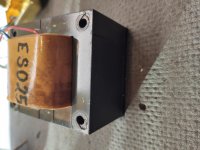
Here's an ES-025 I just pulled apart on my bench. It is nice and tight with the covers off, and the last lams in the stack are flipped around to hold the gap nice and stable.
You would definitely want to know the part number on the transformers you have, as well as whether there's something written with the part number that says something like "20mA" or "40mA".
DS-050s would not be the best choice for a linestage, but could be replaced by a smaller 5K transformer and you could sell the DS-050s for a decent amount of money.
Attachments
Yes, I would do that. I'd also add a "catch resistor" from the grid to ground of about 470K to prevent excess gain, noise or oscillation should the pot's wiper loose contact. It's just good design practice.Hollow do you agree I should swap Tom's volume circuit (input > 300k fixed R > Pot pin 2 and tube pins 5/8, pin 1 open, pin 3 > ground) to the regular volume schematic above?
Yes you may since the secondary has no feedback taken from it. But always keep the "low side" grounded for safety reasons. It doesn't happen very often but should the primary short to the secondary you'd get HV (B+) on the secondary and you definitely don't want that to surprise you.Sans chassis ground, may I invert the output 180 degrees by simply connecting OPT black > RCA pin and yellow > RCA body?
This depends on a couple of factors. Making an ersatz shield (semi shield) by wrapping a signal lead with a ground lead can help reduce hum & noise if the lead length is "long". Or if the overall circuit is, in general, poorly shielded, as not inside a chassis. But if the wiring is fairly short and/or otherwise shielded it's probably not really necessary. And so it basically comes down to how much gain there is, how far apart the connections are, how long the runs are and so on. Some builders do it as a matter course and consider it good practice, others don't. If you have no hum or noise problems, don't sweat it as the saying goes.And should I twist together all audio signal wires with its associated ground?
Nice big picture. It appears that it has been sealed with some type of compound (vacuum impregnation) that's keeping things together. At least for now. I've seen "bookend lams" used many times, but gaped cores could still shift if there's no spacer and that's something you don't want to occur. And yes it is better to "know" then guess. But I've never owned or had my fat little hands on anything Mike ever made so I just tend to be cautious.Here's an ES-025 I just pulled apart on my bench. It is nice and tight with the covers off, and the last lams in the stack are flipped around to hold the gap nice and stable.
Only time I heard this puppy was about 15 years ago!
What is estimated output impedance? (I have a difficult load estimate 9k ohm, main + two sub amps, 12k each.)
Estimated or actual gain?
Does it need snubbers and/or anything you listed in your early reply?
What's your opinion of this circuit?
The 5842 sounded more "firm" and "concise" for lack of a better term vs. the Jadis JPL, though the JPL may have sounded bigger, more grand. My entire system is tons better now, so anxious to plug it in and see later today.
Thanks a ton for your input!
Do you see anything to prevent me from installing a motorized Alps pot? Looks like there's enough real estate. Do those pots normally include a remote mute?
Wize,
I'll disassemble the trafo and report back to class.
If either of you gents have for sale a transformer upgrade, please let me know. Or just tell me what to get. Good to know I may sell these 050 trafos: I'll keep the leads intact.
I'm sure Tom thought these 50s were ideal or he'd not have bought them at the time.
Last edited:
This is just a generalization:
Before disassembling the transformers . . .
If you can look at the laminations of an output transformer,
Then check to see if there is a very thin gap that goes all the way across the width of the lamination stack.
If you can not see the gap, it means one of two things . . .
1. It is a push pull transformer.
Or . . .
2. You need [new] glasses.
With new glasses, if now you see the gap, it is a single ended transformer.
Just one more clue.
If there are only 4 wires, it is single ended, and only has one output tap.
Last edited:
If the picture in Post #3 is your amp,
then you can look on the top of those transformers, and easily see whether there is a gap there or not.
If the transformer is 5k to 600 Ohm, the output impedance is aproximately 200 Ohms (1700 Ohm 5842 rp driving 5k).
If the transformer is 5k to 8 Ohm, the output impedance is less than 3 ohms.
Just a couple of the many possibilities.
Last edited:
Hi 6A3,
Thanks for joining my project!
Unless Tom left some wires hidden which is highly unlikely, trafo sum total:
2 inputs, red and blue
3 outputs, black, orange, yellow
I'm a total believer in output trafo coupled tube line preamps.
Thanks for joining my project!
Unless Tom left some wires hidden which is highly unlikely, trafo sum total:
2 inputs, red and blue
3 outputs, black, orange, yellow
I'm a total believer in output trafo coupled tube line preamps.
Do you have a real good DMM, one with a 100 Ohm or 50 Ohm range.
If so, then short the Red and Blue together.
Then read the 3 output leads.
1 - 2
1 - 3
2 - 3
What are those resistances.
This is probably either a 600 Ohm output with a center tap
or, it is a 0, 4, 8, output.
The DC resistance will be less than 3 Ohms if it is the 0, 4, 8 output
The DC resistance will be much more than 10 Ohms if it is the 600 ohm center tapped output.
Do you have a real good DMM, one with a 100 Ohm or 50 Ohm range.
No; 200 ohm minimum.
If so, then short the Red and Blue together.
Then read the 3 output leads.
1 - 2
1 - 3
2 - 3
black/yellow: 25.25 ohm
black/orange: 19.1 ohm
yellow/orange: 6.45 ohm
What are those resistances.
This is probably either a 600 Ohm output with a center tap
or, it is a 0, 4, 8, output.
The DC resistance will be less than 3 Ohms if it is the 0, 4, 8 output
The DC resistance will be much more than 10 Ohms if it is the 600 ohm center tapped output.
- Home
- Amplifiers
- Tubes / Valves
- Twist audio signal and ground?