Yes, your model needs a fixed DC voltage in series with the screen grid in addition to the feedback voltage.I hope that the attached simulations show clearly what I mean.
For the "ultralinear" simulation I gave E1 source a value of 0.43 instead of 1.
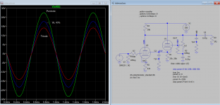
In that case, the curves are lower than for pure triode.
Am I doing something wrong here?
What definition do you subscribe to?
I/V curves that are midway between pure triode and pure pentode modes.
Yes, your model needs a fixed DC voltage in series with the screen grid in addition to the feedback voltage.
As I posted on #19, I know there's has to be a DC voltage. But take a look at the two links to tube cad journal:
The Tube CAD Journal,Ultra-Linear Output Stages
The Tube CAD Journal,Ultra-Linear Output Stages
I don't see any g2 fixed DC voltage. Is there?
Would you consider them as ultralinear circuits?
I don't. The simulation results attached to my first post show I/V curves lower than triode's (and not between triode and pentode mode).
If that is your preferred definition then the Tubecad cascode circuit is not UL, it's just local feedback around the upper triode.I/V curves that are midway between pure triode and pure pentode modes.
However, the Tubecad pentode circuit is UL, since it has a fixed DC voltage applied to the screen in addition to the AC feedback (150V is stored on the .22uF capacitor), so it will be somwhere between triode and pentode mode.
Last edited:
Would this sim helps you to see if it claimed what it does? I hope you compare the UL curve plot to actual UL curve from original manufacturer to see it's any differences, that is the best way I think.
Yes. It helped me to simulate transient response instead of just doing a spice dc simulation.
However, the Tubecad pentode circuit is UL, since it has a fixed DC voltage applied to the screen in addition to the AC feedback (150V is stored on the .22uF capacitor), so it will be somwhere between triode and pentode mode.
Yes, that capacitor is the "magic" that solved the mistery for me.
Thanks for pointing that out, Merlin.
Edit: why that 10 Mohm resistor in grid of the 6SN7 (pentode circuit)?
Last edited:
It is there in case the wiper of the pot does not make good contact with the track, which would leave the grid floating. It's not essential.Edit: why that 10 Mohm resistor in grid of the 6SN7 (pentode circuit)?
It is there in case the wiper of the pot does not make good contact with the track, which would leave the grid floating. It's not essential.
Thank you!
to make a transformerless circlotron with 50% UL, feed ground referenced dc to g2 and ac ground it.
The control grid draws some current from the 40% tap on the output transformer. If B+ is 200v then the output is about 130 to 270 v seen at the grid.
You may need a 2 transistor totem pole to get low impedance drive.
You may need a 2 transistor totem pole to get low impedance drive.
Just take a look at the Don Leslie patent US3005162A (just for fun).
It is not UL but could be modified.
It is not UL but could be modified.
Would this sim helps you to see if it claimed what it does? I hope you compare the UL curve plot to actual UL curve from original manufacturer to see it's any differences, that is the best way I think.
Same thing as I did on the bench circa 1960. See Post 4, this thread.🙂
- Home
- Amplifiers
- Tubes / Valves
- Transformerless ultralinear?