Hi everyone.
I've come across this concept on tube cad journal:
The Tube CAD Journal,Ultra-Linear Output Stages
The Tube CAD Journal,Ultra-Linear Output Stages
Basically, a scaled down anode voltage is feed to the screen (or cascode's upper triode's grid).
AFAIK, this is not ultralinear. Ultralinear is something in between pentode and triode. But just supplying a scaled down voltage to the screen grid makes the triode even more triode.
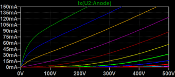
I hope that the attached simulations show clearly what I mean.
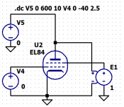
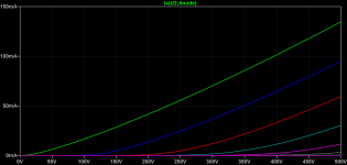
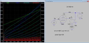
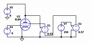
For the "ultralinear" simulation I gave E1 source a value of 0.43 instead of 1.
In that case, the curves are lower than for pure triode.
Am I doing something wrong here?
Thanks!
I've come across this concept on tube cad journal:
The Tube CAD Journal,Ultra-Linear Output Stages
The Tube CAD Journal,Ultra-Linear Output Stages
Basically, a scaled down anode voltage is feed to the screen (or cascode's upper triode's grid).
AFAIK, this is not ultralinear. Ultralinear is something in between pentode and triode. But just supplying a scaled down voltage to the screen grid makes the triode even more triode.
I hope that the attached simulations show clearly what I mean.
For the "ultralinear" simulation I gave E1 source a value of 0.43 instead of 1.
In that case, the curves are lower than for pure triode.
Am I doing something wrong here?
Thanks!
Attachments
I think you could use a resistor based voltage divider, as well. The issue is that g2 draws some current that should be calculated in.
I think you should simulate three cases for better comparison:
- g2 tied to anode (pure triode)
- g2 on fixed voltage (pure pentode)
- g2 tied to scaled down anode voltage (supposed UL)
I think you should simulate three cases for better comparison:
- g2 tied to anode (pure triode)
- g2 on fixed voltage (pure pentode)
- g2 tied to scaled down anode voltage (supposed UL)
I think you should simulate three cases for better comparison:
- g2 tied to anode (pure triode)
- g2 on fixed voltage (pure pentode)
- g2 tied to scaled down anode voltage (supposed UL)
Isn't it what I did? I used a perfect voltage source for g2, to avoid g2 current entering the equation.
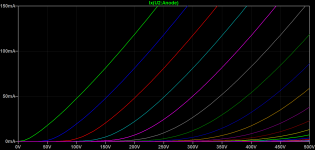
1) Pure triode is simulated with E1 set to 1 (same voltage on g2 than on anode)
2) Suppposed UL is simulated with E1 set to 0.43 (43% of anode voltage fed to g2).
Of course, I get the same triode curves than on case 1) just connecting g2 to anode.

Why is everybody flogging their own pet circuit rather than trying to explain/answer the question of the OP??
I would, if I knew. He knows what he's doing, and the result is not what is expected.
Jan
I would, if I knew. He knows what he's doing, and the result is not what is expected.
Jan
Improved vacuum tube models for SPICE, Part 1
According to the above for correct UL sim VG2 normal voltage should be assigned, but OP does not so that is the difference, hence the interpretation.
According to the above for correct UL sim VG2 normal voltage should be assigned, but OP does not so that is the difference, hence the interpretation.
Attachments
Koonw, can put one of those .asc files here ?
I would like to check some details for learning purpose.
I would like to check some details for learning purpose.
Elerion, can you attache here the .asc-file of you simulation.
Sure
Attachments
Improved vacuum tube models for SPICE, Part 1
According to the above for correct UL sim VG2 normal voltage should be assigned, but OP does not so that is the difference, hence the interpretation.
I know that. But that is not what it's shown on the source website I posted (tube cad journal). Hence my question.
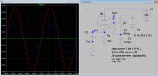
You can just add nominal Vg2 to OP asc. I sim this few months back a little different, thank to OP for the short cut method.Koonw, can put one of those .asc files here ?
I would like to check some details for learning purpose.
Attachments
I know that. But that is not what it's shown on the source website I posted (tube cad journal). Hence my question.
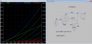
Have to figure out what the Vg2 voltage is of TubeCad sch, then sim it to see if any good.
I am interested to know too so I sim it. Vg2 is about 150V, the pot adjust for % of feedback. Vg2 remains stable when the pot is adjusted.
Attachments
Last edited:
....For the "ultralinear" simulation I gave E1 source a value of 0.43 instead of 1. In that case, the curves are lower than for pure triode....
UltraLinear is a fraction of the load voltage, not the tube voltage.
This is a popular confusion, which has bitten me several times.
It is difficult to patch in your setup because you do not have a "load". There is a way to measure UL curves without a load but I'm too foggy to find it.
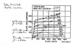
In order to plot a loadline & calc possible power all that is required is the plate current vs voltage while the control grid is at zero volts. That curve is one end of the loadline unless going into grid current. The attachment is something I plotted several years ago on the 6L6GC plate family. It works well but needs some cleanup.
Not the answer asked for but some here might be interested.🙂
I don't have any favorite circuit, they are all simply tools of the art. Nothing more, nothing less. Use as we like to get where we want to go.😀
Not the answer asked for but some here might be interested.🙂
I don't have any favorite circuit, they are all simply tools of the art. Nothing more, nothing less. Use as we like to get where we want to go.😀
Attachments
Agreeing with PRR.
For transformerless UL, dont we need an anode capacitor to isolate the DC? Then just feed the screen DC quiesecent voltage from a Teed divider, the "T" being the summing junction of the AC from anode and the DC network setting Vg2
For transformerless UL, dont we need an anode capacitor to isolate the DC? Then just feed the screen DC quiesecent voltage from a Teed divider, the "T" being the summing junction of the AC from anode and the DC network setting Vg2
Have to figure out what the Vg2 voltage is of TubeCad sch, then sim it to see if any good.
Agreeing with PRR.
For transformerless UL, dont we need an anode capacitor to isolate the DC? Then just feed the screen DC quiesecent voltage from a Teed divider, the "T" being the summing junction of the AC from anode and the DC network setting Vg2
I agree with all that have been said. I designed and built UL amplifiers, and I think I get the point. But please look at the two links:
The Tube CAD Journal,Ultra-Linear Output Stages
The Tube CAD Journal,Ultra-Linear Output Stages
Are those two circuits UL? I don't think so. Hence my question.
It is difficult to patch in your setup because you do not have a "load". There is a way to measure UL curves without a load but I'm too foggy to find it.
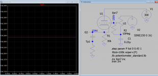
I get the curves without a load just like this (schematic and curves attached).
Why is a load needed to get the I/V curves?
The ultralinear curves shown on some datasheets (like KT88) don't specify any load.
Attachments
There is no strictly universal definition of UL.Are those two circuits UL? I don't think so. Hence my question.
Some people take it to mean ONLY the narrow application proposed by Hafler & Keroes, involving an output transformer with a critically-chosen tapping point feeding the screen, to acheive maximum distortion cancellation.
Others take it to be just another name for distributed loading, again involving an output transformer but where the screen tapping point can be anywhere along it.
Others take it to mean any pentode stage where some feedback is applied to the screen grid, transformer or no transformer.
Others take it to mean any pentode-like circuit (e.g. cascode) where some feedback is applied to the 'screen' grid.
Others take it to mean any circuit at all where feedback is applied to any grid other than the main input grid, and where the feedback is tuned for maximum distortion cancellation.
What definition do you subscribe to?
- Home
- Amplifiers
- Tubes / Valves
- Transformerless ultralinear?