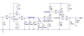
The problem I'm trying to solve is how to make a tube phono stage that will be friendly to current-issue moving-magnet phono cartridges that expect low input capacitance (specs claim input load C should be 250pF, including cable capacitance, strays, and preamp input capacitance).
The obvious solution is of course 'use an opamp'. So....
Why not make the input stage a good opamp like OPA2134, and make the output stage something like a 6DJ8, with the EQ in the middle?
I searched for something like this, and even though I know I can't possibly be the first person to think of this silly idea, I couldn't find much along these lines.
I found this:
Opamp + tube RIAA board art – wauwatosa tube factory
I also found that (of course) John Broskie has played with the idea, here:
Phono Preamps at Last
This interesting circuit is described in that TubeCAD article:

What I dreamed up is much less clever. But will it work? It seems so simple.
Will the approximately 60mV DC to the grid of the second stage 6DJ8 cause problems? Will the opamp output need to be RC-coupled to the 6DJ8? (attached schematic)
--
The obvious solution is of course 'use an opamp'. So....
Why not make the input stage a good opamp like OPA2134, and make the output stage something like a 6DJ8, with the EQ in the middle?
I searched for something like this, and even though I know I can't possibly be the first person to think of this silly idea, I couldn't find much along these lines.
I found this:
Opamp + tube RIAA board art – wauwatosa tube factory
I also found that (of course) John Broskie has played with the idea, here:
Phono Preamps at Last
This interesting circuit is described in that TubeCAD article:
What I dreamed up is much less clever. But will it work? It seems so simple.
Will the approximately 60mV DC to the grid of the second stage 6DJ8 cause problems? Will the opamp output need to be RC-coupled to the 6DJ8? (attached schematic)
--
Attachments
I Don't have experience with phono stage design, but you could reverse the set-up and have the first stage be a tube CF with its attendant minimal input capacitance driving (RC coupled) a common cathode triode stage. The output stage could be another tube CF or a mosfet source follower such as the one Eli Dutman uses for the modified RCA phono pre.
Will the approximately 60mV DC to the grid of the second stage 6DJ8 cause problems?
No problem there, it just slightly changes the Vgk bias voltage by a few percent.
Use higher power supply voltages than 9V to avoid clipping on noise peaks,
and correct C2c for the Miller effect loading, if it isn't already.
But the input impedance seen by the cartridge is 100R, not 47k, since the (-) input
of the op amp is a virtual ground, so a mm cartridge could not drive this load.
You'd have to use a non-inverting op amp instead.
Last edited:
I don't think the input capacitance of a 6DJ8 is anywhere near 250pf...
FWIW, I use a 6N1P input on my RIAA design. It's happy with both the older Stanton 680/Pickering XV-15 and the newer Ortofon 2M blue.
FWIW, I use a 6N1P input on my RIAA design. It's happy with both the older Stanton 680/Pickering XV-15 and the newer Ortofon 2M blue.
Rongon, using that op amp inverting input drastically reduces the input Z. You may only need the 2k filter to eq properly.
rayma and stocktrader200, thank you for alerting me to the change in input Z caused by use of the opamp's inverting input. Of course, it's shunt feedback so the input is made into a virtual ground, and that 100 ohm series resistor becomes almost all of the input Z. I suppose I could experiment with using the opamp non-inverting input, but then the output of the whole thing would be inverted. That probably doesn't matter, actually.
kodabmx, a 6DJ8 has input C plus strays equaling about 100pF, but the cable from tonearm to preamp input will also add maybe 100pF to 150pF. If the cabling has more capacitance than that then there's likely to be a resonant bump in the upper mids/lower trebles.
This is more of a thought experiment than anything else, but as you can see, I'm not good at accounting for all the various side effects of the various circuits. Thanks for helping me learn about this stuff. I appreciate it!
--
With the phono circuit as-is, it is overall non-inverting due to the two inverting stages in series.
I had a Numark TT that had 1000pf soldered across it's outputs... I promptly removed them. The highs improved 🙂 Then I sold the TT and got an old Toshiba.
With the headshell removed, I test my TT cable to be 0.048nF. My cart wants ~275pF. Seems like it might even be underloaded...
With the headshell removed, I test my TT cable to be 0.048nF. My cart wants ~275pF. Seems like it might even be underloaded...
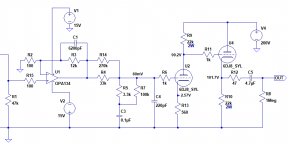
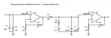
OK, here it is patched up.
Non-inverting input used on the opamp.
The idea is to make a 'tube' preamp with controllable input capacitance. The THD isn't that low (LTspice says 0.05% with 5mV RMS input).
I'd add a 1N4148 from the cathode follower grid to cathode, to limit cathode-heater voltage at turn-on. Also bias the heater up about +50V or thereabouts.
That might fly, right?
--
Attachments
With the headshell removed, I test my TT cable to be 0.048nF. My cart wants ~275pF. Seems like it might even be underloaded...
I should try that. What kind of cap meter did you use? I only have a handheld LCR meter. Would that work?
If you're using a Stanton 681 or Pickering XV15, their recommended load is about 275pF. I have a couple of those with Jico stylus replacements, but I just got an Audio Technica VM95E and I actually like it quite a lot. I'm using a Hagerman Bugle right now, and am slowly building up a 12AX7-12AX7-ZVN0545(source follower) RIAA on a couple of MerlinB's PCBs. It will be interesting to see how the AT cart works into a 12AX7.
--
Non-inverting input used on the opamp.
In this topology C4 is not used. I haven't checked the remaining component values in the passive RIAA.
The cartridge load C should be in parallel with the 47k.
My TT cable with headshell removed measures about 150pF. It's a fancy Cardas cable too.
The Y-cable I use to put a resistor in parallel to play with loading adds about 70pF to that (total of about 220pF).
The input capacitance of a 12AX7 is usually about 150pF.
That would make up to a 400pF load on the cartridge using an unlucky 12AX7.
From Aiken Amps site:
The Y-cable I use to put a resistor in parallel to play with loading adds about 70pF to that (total of about 220pF).
The input capacitance of a 12AX7 is usually about 150pF.
That would make up to a 400pF load on the cartridge using an unlucky 12AX7.
From Aiken Amps site:
a typical 12AX7 stage has the following capacitances and gain:
Cgk = 1.6pF + 0.7pF stray = 2.3pF
Cgp = 1.7pF + 0.7pF stray = 2.4pF
A = 61
Therefore, the total input capacitance would be:
Cin = 2.3pF + (61+1)* 2.4pF = 151.1pF
In this topology C4 is not used. I haven't checked the remaining component values in the passive RIAA.
The cartridge load C should be in parallel with the 47k.
I threw C4 in there to add a LPF for frequencies >100kHz. LTspice shows a huge bump in amplification up in the 1MHz range, which looks pretty scary. Of course that might not happen in real life. I'd build it without C4 and only add it if necessary.
I used John Broskie's TCJ RIAA app to get RIAA component values, and LTspice to double-check.
Agreed, cartridge loading C would go in parallel with R1 (47k ohms).
--
I should try that. What kind of cap meter did you use? I only have a handheld LCR meter. Would that work?
If you're using a Stanton 681 or Pickering XV15, their recommended load is about 275pF. I have a couple of those with Jico stylus replacements, but I just got an Audio Technica VM95E and I actually like it quite a lot. I'm using a Hagerman Bugle right now, and am slowly building up a 12AX7-12AX7-ZVN0545(source follower) RIAA on a couple of MerlinB's PCBs. It will be interesting to see how the AT cart works into a 12AX7.
--
I just used a handheld meter that has capacitance.
Using the numbers from the datasheet and Aiken site formula, I get Cin~40pF using 6N1P.
The Jico Vividline is an amazing value on the Pickering. I prefer it to the 2M Blue.
It'll work alright into a 12AX7, but you might find you like the 6N2P better - and they cost less.
Last edited:
I threw C4 in there to add a LPF for frequencies >100kHz. LTspice shows a huge bump
in amplification up in the 1MHz range, which looks pretty scary.
That bump is from the op amp using the non-inverting mode. At high frequencies its gain
approaches unity, instead of further declining toward zero as would be preferable.
kodabmx said:It'll work alright into a 12AX7, but you might find you like the 6N2P better - and they cost less.
I have a pretty good collection of vintage 12AX7s, including RCA 7025, Telefunken flat plates, a few Mullard, Sylvania, etc. I was hoping I could use some of 'em. I used to have a few 6EU7, but I can't find them. Maybe I sold those off.
rayma said:That bump is from the op amp using the non-inverting mode. At high frequencies its gain approaches unity, instead of further declining toward zero as would be preferable.
Is it necessary to compensate for that? If so, what's the commonly accepted way to do that?
--
Using an opamp at the input is attractive because that can give you as much gain as you need with not a lot of Cin, practically zero THD, and very low output impedance. It's all very predictable.
After that, I could add the tube of my choice, for 'flavor'. I like 6DJ8s in phono preamps because they have an 'exciting' sound with lots of apparent 'detail'. (I think it's from the harmonic content of the distortion they add. It seems I like it.) Starting with the clean amplification and accurate EQ from an OPA2134, it could be nice to sweeten that up with some 6DJ8 style THD.
Also, I have a good stock of 6DJ8 and 6922, which I'd like to put to use.
--
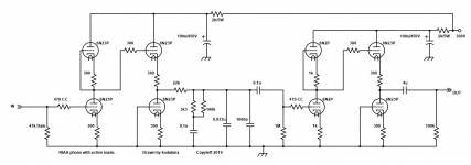
Here's what I would build if I had 6DJ8 (6N23P) and 12AX7 (6N2P)
The second idea was one I drew up that is the opposite of what you're thinking. Simply swap the gain stages around and voilà.
Or ditch the tubes entirely and go with the third one 😛
The second idea was one I drew up that is the opposite of what you're thinking. Simply swap the gain stages around and voilà.
Or ditch the tubes entirely and go with the third one 😛
Attachments
Last edited:
Idea 1 is basically a simplified Aikido Phono Stage, no? The active load ('half-mu') stage has half the gain of a common cathode amp, which would probably push me to put a 12AX7 or 6N2P for the first two stages.
The second one is interesting. However, in a phono stage, don't you want as much clean gain as possible up front in the first stage, to reduce noise? Interesting idea to use 6BQ7 as the input tube...
The third one is basically the same as the Bugle, but using a different opamp (I'm using OPA2134s). It's pretty good, actually.
The problem I'm trying to solve is how to make a tube phono stage that will be friendly to current-issue moving-magnet phono cartridges that expect low input capacitance (specs claim input load C should be 250pF, including cable capacitance, strays, and preamp input capacitance).
The obvious solution is of course 'use an opamp'.
I disagree. High CMiller at the I/P is the fundamental problem. Eliminate that problem with either a 6922 cascode or (if you're "adventurous") a 6AC7 pentode in the 1st gain block. Your 12AX7 collection provides the 2nd gain block. Add some sort of voltage follower to drive the downstream load.
- Home
- Amplifiers
- Tubes / Valves
- Possibly silly idea - Opamp input-Triode w/ Cathode Follower Output RIAA Phono Stage