What is the difference between offset horn and a stubbed horn?
I see both as options in Hornresp but a simple Google search doesn't return anything for a stubbed horn and I can't visualise what it is from the circuit diagram in Hornresp.
Clarification is much appreciated.
I see both as options in Hornresp but a simple Google search doesn't return anything for a stubbed horn and I can't visualise what it is from the circuit diagram in Hornresp.
Clarification is much appreciated.
What is the difference between offset horn and a stubbed horn?
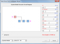
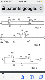
Attachment 1 shows an offset driver horn. The horn has three segments (H1, H2 and H3) and an offset driver (D). The throat of the horn is closed.
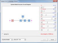
Attachment 2 shows a stubbed horn. The horn has three segments (H1, H2 and H3) and an offset stub H4. The mouth of the stub is closed. The driver (D) is not offset.
a simple Google search doesn't return anything for a stubbed horn
Try Googling 'transmission line stub' instead.
Attachments
Last edited:
Didn't help for acoustic stubs, but assume we're talking about a band-stop filter to damp a peak since it's closed: http://users.cms.caltech.edu/~ps/All.pdf
GM
GM
Didn't help for acoustic stubs
Electrical and acoustical transmission line stubs are effectively analogous.
True as the pioneers proved and how you design/program HR, but how many folks on an audio forum see/use an electrical equivalence ckt. when wanting to design a speaker cab?
GM
GM
but how many folks on an audio forum see/use an electrical equivalence ckt. when wanting to design a speaker cab?
I suspect that not too many would see/use an acoustical equivalent circuit either... 🙂.
I thought that the more readily available information on electrical stubs would hopefully give Giri a reasonable idea of what purpose a stub serves - the basic principles being essentially the same as those for acoustical stubs.
Attachment 2 shows a stubbed horn. The horn has three segments (H1, H2 and H3) and an offset stub H4. The mouth of the stub is closed. The driver (D) is not offset.
Try Googling 'transmission line stub' instead.
Did I understand it right that a stubbed horn is an FLH with a quarter wave transmission line(stub) attached somewhere down the length of the horn?
What is the engineering purpose of such a stub?
Because the diyAudio Search feature is still not working (at the time of this post), use Google instead and search for 'site:diyaudio.com stub' to find the answers to your questions.
Because the diyAudio Search feature is still not working (at the time of this post), use Google instead and search for 'site:diyaudio.com stub' to find the answers to your questions.
Will do. Thanks.
Giri, it’s pretty neat!! try them as a contribution (unstuffed or lightly) and akso as an absorber(heavily stuffed). pretty sure you’ll like a lot of things you can mess around with....
Attachments

If you find any good examples, please post them Giri🙂
The only stub I managed to figure out till now is offset ing a transmission line driver to 1/3rd along the line
Fully offset the driver. then place a bass reflex behind it from
The opposite side of the cone. Size it so it is NOT just a higher tuned TL(short).
ask Martin King if you dont find me helpful. He can explain, if you get lucky and dont **** his ego off trying to ask him. in other words, try it yourself and see, then take it to him. Prepare to be removed from his facebook page though...
He wants that to be his next moment or idea to show us all how we are dumber than him.. unfortunately, he didnt realize we were already figuring it out while he calmed down from whatever happened to him 10(?) years ago?? I dunno, but the man is bitter sweet. i owe him a lot for all the learning he gave me and he can pretend only he knows it or appreciates it no matter what i try and show him as a result of that(and anyone else has too) ... a gift he cant even appreciate the rewards of. we are all just harmonics to him... he is the fundamental. and he doesnt even like qw, he mass loads it, lol!!!
The only stub I managed to figure out till now is offset ing a transmission line driver to 1/3rd along the line
The vent is another one. 😉
Note that driver, vents ideally need to be at an acoustic odd harmonic, so more to choose from depending on the desired performance.
GM
The vent is another one. 😉
Note that driver, vents ideally need to be at an acoustic odd harmonic, so more to choose from depending on the desired performance.
GM
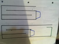
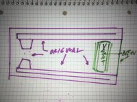
I havent ‘mastered’ this one ‘yet’. But ill be darn if it isnt an absolutely wonderful thing in a ‘Regular ‘TL’. so much so that i am Trying to find the sweet spot in higher order versions (pic): Its there, i cant quite figure it out though. Hard to bolt on various ‘windows’ to decifer whats changed for what reason.
Attachments
Seems like you'd want the vent at ~L*0.848 or the very end since the drivers appear to be ~1/3 down.
GM
GM
Seems like you'd want the vent at ~L*0.848 or the very end since the drivers appear to be ~1/3 down.
GM
Your the best

- Home
- Loudspeakers
- Subwoofers
- Stubbed horn?