Welcome IgnacioCal! You'll find the best info at this specific topic: Amp Camp Amp - ACA
That said, I do believe the ACA has some gain of its own, so the SYS would work for adjusting volume. It'll also depend on what source you use, and how much output its passing along through the SYS. Whether its ultimately enough volume will depend on your speakers and listening preferences.
That said, I do believe the ACA has some gain of its own, so the SYS would work for adjusting volume. It'll also depend on what source you use, and how much output its passing along through the SYS. Whether its ultimately enough volume will depend on your speakers and listening preferences.
Last edited:
Thanks for the feedback Cody !!
Checking in the forum that you suggested i confirmed that the Shiit is a good option for the purpose
best,
Ignacio
Checking in the forum that you suggested i confirmed that the Shiit is a good option for the purpose
best,
Ignacio
Hey guys. So I'm almost done soldering my ACP+, but I have a question.
If I'm using an external volume control, which pot pads do I need to jumper?
When looking at the top of the board, with pot closest to me
Top right to top middle? and
Bottom right to bottom middle?
If I'm using an external volume control, which pot pads do I need to jumper?
When looking at the top of the board, with pot closest to me
Top right to top middle? and
Bottom right to bottom middle?
I would say left-to right - one is the pot‘s input, the other out... (noob myself, so grain of salt [emoji6])
Looking at the top: left = Ground, middle = out to circuit, right = in, from selector switch
Last edited:
Looking at the top: left = Ground, middle = out to circuit, right = in, from selector switch
Thought so, thanks! 🙂
Looking at the top: left = Ground, middle = out to circuit, right = in, from selector switch

Or you could install the pot and just keep it wide-open. Does the exact same thing as jumpering.
Or you could install the pot and just keep it wide-open. Does the exact same thing as jumpering.
Yeah that would've been my first choice, but I don't have the pot yet.
Mouser was out of the RK27 pot in the correct value when I ordered. I also ordered 200R trimpots for R4 so I can figure out the exact correct value of R4 for my J113s. Once I figure out the optimal values of R4, I'm going to order fixed resistors to replace the trimpots.
So, in the interest of paying shipping only twice instead of 3 times, I decided to wait to order the pot at the same time I order the R4 resistors, as opposed to ordering the pot separately from Parts-Express or another vendor.
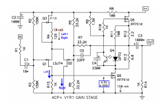
R4 adjustments
Is getting R4 exactly right a requirement or OCD? What the impact if the J113s aren’t matched and the R4 aren’t adjusted?
Is getting R4 exactly right a requirement or OCD? What the impact if the J113s aren’t matched and the R4 aren’t adjusted?
Is getting R4 exactly right a requirement or OCD? What the impact if the J113s aren’t matched and the R4 aren’t adjusted?
First of all, I definitely have OCD. 😀 I’m not sure I’ve met an audiophile who doesn’t. 😛
But I did this because I saw some others earlier in the thread talking about matching J113s or adjusting R4.
Also, there’s this sentence on pg5 of Nelson’s ACP+ article:
“In the case of R4, the J113 Jfets I had in stock had a higher Vp, so the value is adjusted from 68 ohms up to 125 ohms to give the 10 mA current source value.“
So the goal was to get the current through R4 dialed in to 10 mA.
But I’m not qualified to say whether all of this is strictly necessary or what the implications of not matching Q3 to R4 are. Hopefully someone else more knowledgeable will chime in.
But I’m not qualified to say whether all of this is strictly necessary or what the implications of not matching Q3 to R4 are. Hopefully someone else more knowledgeable will chime in.
Now I'm wondering too. Anyone?
Had to look um "OCD" first...
I have matched Q3 to R4. And I definitely suffer from "matching OCD". I think you should be in the range of around 10 mA for each channel.
See my post #491
Best,
Ulf
I have matched Q3 to R4. And I definitely suffer from "matching OCD". I think you should be in the range of around 10 mA for each channel.
See my post #491
Best,
Ulf
Perhaps there's a different way to think about the "optimum" value of DC current flowing in the Long Tail Pair bias transistor, Q3.
It might be a little tidbit for the OCD perfectionists to get lathered up about. (relevant link)
You could measure VGS(Q6) of your unit and figure out the exact value of "delta" of YOUR ACP+. Plug it into the equations above and Bob's Your Uncle, you know the optimum IdsQ3. Repeat for the other channel since it's a stereophonic device.
_
- Each and every IRFP610 that rolls off the manufacturing line, is slightly different. In particular, each one has a slightly different gate turn-on voltage ("Vthreshold").
- The ACP+ circuit uses Nelson Pass's patented optoisolator bias control system , to set the gate voltage of Q6 to whatever voltage is necessary in order to make its drain current become Nelson's desired value: 150 milliamps.
- The opto bias compensates for variations among the millions of individual IRFP610's that could be plugged into position Q6
- The expected gate voltage of Q6, for most of the units shipped by the MOSFET factory, at most operating temperatures, is about 4.5 volts. Plus or minus some unit-to-unit variability that I will call "delta".
- So the current flowing in resistor I1 is (4.5V ± delta) / 1K
- If the Long Tailed Pair Q1+Q2 is operating in perfect balance, then the current in Q1 ("Left") is perfectly balanced with the current in Q2 ("Right")
- So the tail current which gives perfect balance, is 2 * (4.5V ± delta) / 1K
- And perhaps we can call that the "optimum" current in Q3.
It might be a little tidbit for the OCD perfectionists to get lathered up about. (relevant link)
You could measure VGS(Q6) of your unit and figure out the exact value of "delta" of YOUR ACP+. Plug it into the equations above and Bob's Your Uncle, you know the optimum IdsQ3. Repeat for the other channel since it's a stereophonic device.
_
Attachments
Last edited:
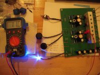
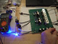
ACP+ experience
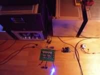
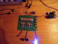
Hello amplifionados,
I started my ACP+ this evening first time. This babe sounds really good.
I need more listening. Also listened with my headphones (250Ohm cans) -
adjusted resistor at output from 33.2 ohm to 37 ohm (switchable) for the headphone
I made a little linear regulated power supply with LT1085 and RCRC-filter.
Voltage adjustable and exactly 24 V.
Voltage at DC1 is at 11 v and 11.1V.
Over R15 I measure 4.44V.
My R4 value is at around 40 Ohm (33 Ohm resistor + 100 Ohm- trimpot dialed down close to zero)
JFets are at around 30C temerature. Mosfets run hot at around 60 - 65C.
Mosfet - heatsink is at around 35C.
Greets
Dirk
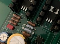
Attachments
![DSCN2047[1].jpg](/community/data/attachments/801/801438-85147d9f2b42d08e396f3f025855140b.jpg?hash=hRR9nytC0I)


 Dirk
Dirk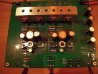
- Home
- Amplifiers
- Pass Labs
- Amp Camp Pre+Headphone Amp - ACP+