Hi folks,
This is an advanced question about playing with or the possibility of exceeding maximum g2 datasheet specs.
The problem with melting down the screen grid lies mostly in the tetrode and pentode connection in the event where the anode is at lowest voltage during maximum tube conduction.
In triode mode the screen swings together with anode, but the problem still exists a bit due to the screen being closer to the cathode. Although higher screen voltages could be applied on many tubes.
But... What is the real case with music - where we (if we got sane minds) rarely it crank up until to the point of severe clipping? If the later doesn't occur, then g2 should be pretty safe at even a bit violated datasheet voltages, no?
I don't see a problem of violation with application of UL as well, where it can be considered as a percentage of going easy on g2.
Troublesome should be of course guitar amplifiers. But we're talking about HiFi here.
Hi,
I can tell you that I used KT150 tubes PP with UL. With 600 VDC and 220 Ohm resistors from UL taps to G2 I saw red glowing screen grids (nothning was visible on the plates). With 1220 Ohm (220 Ohm + 1K) the G2 is safe and stable again for HiFi use.
Regards, Gerrit
I can tell you that I used KT150 tubes PP with UL. With 600 VDC and 220 Ohm resistors from UL taps to G2 I saw red glowing screen grids (nothning was visible on the plates). With 1220 Ohm (220 Ohm + 1K) the G2 is safe and stable again for HiFi use.
Regards, Gerrit
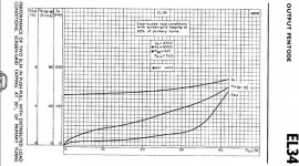
Ultra Linear Example:
500V B+
40% screen tap.
DCR drop to UL tap, 10V, Screen at 490V
DCR drop to Plate tap, 25V, Plate at 475V
Large signal to Control Grid
Plate at 50V
Screen at 320V
Look at the set of tube plate curves for 300V Screen, and the Screen
current when the plate is at 50V.
There will be lots of Screen current.
Probably OK for most music on a Hi Fi.
Perhaps Not OK for a Guitar amplifier that is being maxed out.
Last edited:
When comparing the 30W numbers to the 0W here, Ik changes 20mA. Is that solely due to G2 current? What is the impact of Rg2 size on total distortion? How about autobias against fixed bias?
Attachments
Last edited:
the g1 voltage has more impact than g2 in most cases...
imho, you can go above the g2 dissipation provided the duration of the event is very very short...
imho, you can go above the g2 dissipation provided the duration of the event is very very short...
In any case, I'd say, is the controld grid's impact larger than the screen's. The datasheet µg2g1 value describes the relation.
Best regards!
Best regards!
When comparing the 30W numbers to the 0W here, Ik changes 20mA. Is that solely due to G2 current? What is the impact of Rg2 size on total distortion? How about autobias against fixed bias?
The Mullard datasheet that contains the diagram you posted, seems to answer your first question. Ig2 at no signal is 2 x 9 mA. Ig2 at full signal (40 Watt) is also 2 x 9 mA. So probably Ig2 is also 2 x 9 mA at 30 Watt.
Attachments
In a P-P amp, you will almost always exceed the pg2 rating on the top half of each cycle at Or even just before clipping. The average is what is important, and unfortunately, not necessarily easy to directly calculate. Unless you have a very good spice model (unlikely that good) or are willing to do graphical/numerical integration from IV curves. If you stay in the ballpark of data sheet conditions where (average) ig2 is given you’re probably ok. Stray too far and you have to measure it. In any case, how high the dissipation gets will depend most heavily on how hard you beat on it. Stay away from frequent clipping and don’t exceed Vg2 ratings your probably not exceeding ig2/Pg2 on average. Guitar amps often exceed pg2, even on average, and that’s one reason they go through tubes like water.
Exactly guys. In Hi-Fi we stay away from clipping and if an overload occurs, it's most likely a peak in music.
My issue comes when trying to use some tubes in SE output stages with local feedback. If the gain of the stage is too low, I need often to operate the tube at higher current for the quiescent point to stay in the middle of the loadline. But for some tubes a higher g2 voltage is needed. Hence the need to violate some datasheet rules.
My issue comes when trying to use some tubes in SE output stages with local feedback. If the gain of the stage is too low, I need often to operate the tube at higher current for the quiescent point to stay in the middle of the loadline. But for some tubes a higher g2 voltage is needed. Hence the need to violate some datasheet rules.
Interesting data from the old masters:
The Telefunken data-sheet for the EL34 has this table under "two tubes push-pull operation".
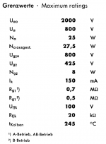
Now have a look at the right most column for 800V B+
Ig2 with full signal (German: "ausgesteuert") is given as 19mA per tube, average, which gives Pg2 of no less than 14 Watts !
Thats almost 2x the max ratings of 8 Watts on the next page.
If we calculate plate dissipation from that table, we get 71 Watts, almost 3x of the max 27.
It is quite clear that whoever wrote this data-sheet did not have sine testing in mind, but was well aware of the crest factor present in music or pa programme.
https://frank.pocnet.net/sheets/128/e/EL34.pdf
The Telefunken data-sheet for the EL34 has this table under "two tubes push-pull operation".
Now have a look at the right most column for 800V B+
Ig2 with full signal (German: "ausgesteuert") is given as 19mA per tube, average, which gives Pg2 of no less than 14 Watts !
Thats almost 2x the max ratings of 8 Watts on the next page.
If we calculate plate dissipation from that table, we get 71 Watts, almost 3x of the max 27.
It is quite clear that whoever wrote this data-sheet did not have sine testing in mind, but was well aware of the crest factor present in music or pa programme.
https://frank.pocnet.net/sheets/128/e/EL34.pdf
Attachments
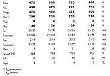
Ubg2 = 400 V
Ig2 at full signal per EL34 = 19 mA
So Pg2 at full signal for one EL34 = 0.019 x 400 = 7.6 Watt. So under the limit of 8 Watt.
Ig2 at full signal per EL34 = 19 mA
So Pg2 at full signal for one EL34 = 0.019 x 400 = 7.6 Watt. So under the limit of 8 Watt.
1st: Pg2 calculates to 400 V * 19 mA = 7.6 watts, what is ok.
2nd: Pa calculates to 800 V * 91 mA - 50 W = 22.8 watts, which also is ok.
Btw, plate dissipation has it's peak not at maximum power, but at about two thirds of it.
Best regards!
2nd: Pa calculates to 800 V * 91 mA - 50 W = 22.8 watts, which also is ok.
Btw, plate dissipation has it's peak not at maximum power, but at about two thirds of it.
Best regards!
Simply add an extra 50V power supply to g2? Regulated if you want so it keeps track with the main psu.My issue comes when trying to use some tubes in SE output stages with local feedback. If the gain of the stage is too low, I need often to operate the tube at higher current for the quiescent point to stay in the middle of the loadline. But for some tubes a higher g2 voltage is needed. Hence the need to violate some datasheet rules.
The peak ig2 hits 100mA or more when the plate pulls down to 50 volts at the top of the sine wave. It only happens over a short period of time - a small fraction of each cycle. When you slam the amp and make it put out square-ish waves you will go over 19mA on average. Still pretty hard to do with music.
I still only get 22W for the max plate dissipation, B+/(2.5*Ra-a), which theoretically does occur around 2/3 power. With a knee voltage between 50 and 100 volts, the dissipation doesn’t drop much at “maximum” power like a solid state amp would. Too much IR drop in the tube, even as a pentode.
I still only get 22W for the max plate dissipation, B+/(2.5*Ra-a), which theoretically does occur around 2/3 power. With a knee voltage between 50 and 100 volts, the dissipation doesn’t drop much at “maximum” power like a solid state amp would. Too much IR drop in the tube, even as a pentode.
In any case, I'd say, is the controld grid's impact larger than the screen's. The datasheet µg2g1 value describes the relation.
Best regards!
yes since the g1 is where the signal entered and the g2 is somewhat fixed in voltage......unless it was a smoking amp crazy drive or screen drive amp ala Berning....
Pa calculates to 775V*91mA 50W = 20.5W1st: Pg2 calculates to 400 V * 19 mA = 7.6 watts, what is ok.
2nd: Pa calculates to 800 V * 91 mA - 50 W = 22.8 watts, which also is ok.
Btw, plate dissipation has it's peak not at maximum power, but at about two thirds of it.
Best regards!
In reality, both, Pa and Pg2 at full power out will be lower because
100W is not possible to get with a sensible 800V power supply.
A supply where a center tapped winding feeds the bridge for the anode voltage and Ug2 is taken from the tap.
My take is that the 100W mentioned in the datasheet could only happen in the lab with lab power supplies
Last edited:
Yeah, any real 800 volt supply is going to drop some under load - probably giving you around 700. You could get “better regulation” with a choke input supply, but the fact of the matter is their real regulation factor is quite poor. If your amp is drawing over the critical current, regulation is pretty decent. But at start up you WILL see 1100 volts which is pushing the boundaries of safety on tubes without anode caps. Perhaps for the rest of the wiring as well.
1st: Pg2 calculates to 400 V * 19 mA = 7.6 watts, what is ok.
2nd: Pa calculates to 800 V * 91 mA - 50 W = 22.8 watts, which also is ok.
Btw, plate dissipation has it's peak not at maximum power, but at about two thirds of it.
Best regards!
Actually, Pg2 is less than 7.6W beacuse you have voltage drop on common 750ohm resistor for both g2.
750 * 0.038 = 28.5 V
400 - 28.5 = 371.5 V
so:
371.5 V * 0.019 mA = 7.0585 W
No, you don’t calculate the drop in the resistance from the average current. The IR drop is instantaneous (it says non-decoupled g2). The peak currents are way above the 19 mA average. You have to do a bunch on numerical integration on the ig2 curves to get the actual average (or rms) values. Have fun with that. And the drop in the g2 stopper peaks for each tube on alternate half cycles - they don’t really “combine”. When one is up the other is down.
- Home
- Amplifiers
- Tubes / Valves
- g2 instantaneous overload, power dissipation, questions