Exicon datasheet mentions protection diode without being specific as to its characteristics. The body diode is mentioned as a separate item.
Very true. The internal diodes are badly needed to protect the thin dielectric layer, zener diodes generate nasty distortion, are pretty much worthless (slow reaction), luckily, not needed.Originally Posted by N101N View Post
This topology should be stable without any phase compensation capacitor. Zener diodes are far too slow and provide no protection against transient voltages. The lateral FETs have internal protection diodes.
BesPav,
you are hopelessly missing the points of relevance.
It´s all about maintaining the rapidly falling bandwidth.
The EF-triple is a low bandwidth (poor high frequency perfomance) compound.
These are fakes. The 2SC2690 is not an amazing voltage amplifier. NEC did not make (m)any amazing transistors for audio.Ksa1381/ksc3503 are in small production and available now for VAS output and OPS low-capacitance input.
Ksa1220a/ksc2690a are perfect powerful drivers for mostly all home audio amplifiers up to 500wt/8ohm power.
These are fakes. The 2SC2690 is not an amazing voltage amplifier. NEC did not make (m)any amazing transistors for audio.
Rubbish. All four are manufactured right now by Fairchild, and sold by Mouser, Digikey, etc.
It´s all about maintaining the rapidly falling bandwidth.
All of them are at least an order than enough in terms of bandwidth for audio.
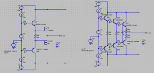
But cct1 have stable OPS poles and are perfect for designing modern amps with complicated freq correction while cct2 have them wildly bouncing and could be accepted only for unassuming switching supply.
The EF-triple is a low bandwidth (poor high frequency perfomance) compound.
No, man. Be honest with yourself.
You just lack of knowledge to cope with it.
The 2SC2690 is not an amazing voltage amplifier.
This is driver trannie, you even can't differentiate voltage and current amplifiers.
After a long time using hi speed, hi Ft Japanese transistors (KSC2690A, KSC3503, 2SC3600, 2SC3423...) I found that MJE340 is the most suitable transistors as driver duty for lateral MOSFETs. Because of its sounding. They keep output sounding of MOSFET become more open, clearly, more neutral. Maybe it can be reason why Goldmund, a hi-end manufacturer usually used it for their products with Exicon lateral MOSFETs.
At lower supply voltages, below +-50VDC i use MJE243/253. The output sounding even better, very very neutral.
However, there is one special case, the Telos 5000. Goldmund uses Fairchild KSC2690A/KSA1220A driving total 36 pairs ECX10N20 as balance mode.
At lower supply voltages, below +-50VDC i use MJE243/253. The output sounding even better, very very neutral.
However, there is one special case, the Telos 5000. Goldmund uses Fairchild KSC2690A/KSA1220A driving total 36 pairs ECX10N20 as balance mode.
Suzy,
It depends on how we define authenticity in this context. Given the delicate nature of the semiconductor manufacturing, which has become rather a shady business, there is reason to adopt stringent criteria.
It depends on how we define authenticity in this context. Given the delicate nature of the semiconductor manufacturing, which has become rather a shady business, there is reason to adopt stringent criteria.
Returning to the question about protection diodes, I asked Profusion:
Regarding the specifications for your range of lateral mosfets:
Is the 'Integral protection diode' mentioned just the drain-source diode, protecting against reverse bias, or is there also a gate-source over-voltage protection? The similar Renesas devices include a pair of back to back zeners for that purpose, do yours also? If so what is their maximum current rating?
The reply:
Yes the Exicon MOSFETs include back to back Zener diodes around 14V but they are not tested in production and therefore no specifications are included on the data sheet.
The size would rate them around 1W.
BesPav,
Corroborated by solid evidence, it is now a freaking scientific fact that the Darlington pair suffers from a narrow bandwidth.
¤
As has been euphemistically stated, the harmful Miller capacitor is an unmistakable symptom of the widespread Insufficient Bandwidth Disease (IBD).
Corroborated by solid evidence, it is now a freaking scientific fact that the Darlington pair suffers from a narrow bandwidth.
¤
As has been euphemistically stated, the harmful Miller capacitor is an unmistakable symptom of the widespread Insufficient Bandwidth Disease (IBD).
Corroborated by solid evidence, it is now a freaking scientific fact that the Darlington pair suffers from a narrow bandwidth.
I can't agree with this common knowledge and scientific facts without proper argues.
Let's dive in the problem.
First. Bandwidth.
Assume 330k VAS load resistance and no correcting capacitance from VAS output point (bad and uncommon, but let's check).
OOPS.
Vague nonsense as you say.
Attachments

Anticdodal imo, a transistor acting as a EF, having a sound characteristic with no explanation as to why that is? Sorry I need more convincing and tests to convince me 🙂After a long time using hi speed, hi Ft Japanese transistors (KSC2690A, KSC3503, 2SC3600, 2SC3423...) I found that MJE340 is the most suitable transistors as driver duty for lateral MOSFETs. Because of its sounding. They keep output sounding of MOSFET become more open, clearly, more neutral. Maybe it can be reason why Goldmund, a hi-end manufacturer usually used it for their products with Exicon lateral MOSFETs.
At lower supply voltages, below +-50VDC i use MJE243/253. The output sounding even better, very very neutral.
However, there is one special case, the Telos 5000. Goldmund uses Fairchild KSC2690A/KSA1220A driving total 36 pairs ECX10N20 as balance mode.
Ther's no Cre in MJE340 datasheets, I guess it's higher then 1.8pF of KSC3503 and hfe is also not the same, so you have different VAS loads... It depends on lot of things so it could sound different, that's no surprise.
Just curious if anyone knows anything about the other Lateral MOSFET pairs from
Hitachi/Renesas: 2SK2221/2SJ351 and 2SK2222/2SJ352? Compared to the other laterals mentioned here so far, the specs are somewhat similar except the capacitances are larger.
Bigger protection diodes maybe?
2SK2222
2SJ352
ECX10N20
ECX10P20
2SK1058
2SJ162
2SK135
2SJ50
Hitachi/Renesas: 2SK2221/2SJ351 and 2SK2222/2SJ352? Compared to the other laterals mentioned here so far, the specs are somewhat similar except the capacitances are larger.
Bigger protection diodes maybe?
2SK2222
2SJ352
ECX10N20
ECX10P20
2SK1058
2SJ162
2SK135
2SJ50
Corroborated by solid evidence, it is now a freaking scientific fact that the Darlington pair suffers from a narrow bandwidth.
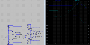
Now some words about from EF-triple really suffers.
Not a narrow bandwidth but intrinsic instability.
Even 500pf load capacitance will make EF-Triple unstable.
While MOS buffer being really a 2-follower EF+SF are stable at much more 10n the EF3 makes mostly all bad-designed amplifiers (yes, the Miller ones) oscillate wildly up to PCB traces naturally burn.
Attachments
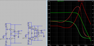
The typical cure for such an instability is a making unstable EF-Triple to become stable EF-Double at high freqs.
Just turn off first EF stage by adding C2+C3 and EF3 becomes much more predictable with slow damped peak and relatively slow phase reversal.
Just turn off first EF stage by adding C2+C3 and EF3 becomes much more predictable with slow damped peak and relatively slow phase reversal.
Attachments

BesPav,
The expression "scientific fact" is nonsense, all right.
I don`t agree with your analysis.
Basic relationships: as amplitude increases, instability increases, current increases and frequency increases - exhausting the bandwidth.
Bandwidth can be seen as an indicator of amplifier`s ability to produce healthy charges usable for signal generation. The lack of bandwidth (polarization) provides a breeding ground for standing waves ("oscillations") confined within high impedance barriers. Smaller amplitudes require less bandwidth, the wide use of the voltage follower lies in its stability and troublefree implementation.
(Bandwidth) Measurements executed under unrealistic static "no load" conditions have little relevance. The real life performance that matters and that cannot be measured.
¤
The topology of CCT2 is qualitatively superior to those suggested as an alternative in this thread.
¤
Oftentimes I dislike my own wording. By "Miller capacitor" I meant an externally applied phase compensation capacitor. The term "Miller effect" is, however, OK.
EF is potentially unstable with the capacitive load. It's a textbook example.
For instance:
"The high current gain of the CC configuration allows it to supply the high transient currents required to quickly charge the capacitive load. When capacitive loading is combined with base resistance, a hf resonance can occur." Dennis L. Feucht, Handbook of Analog Circuit Design, 1990
For instance:
"The high current gain of the CC configuration allows it to supply the high transient currents required to quickly charge the capacitive load. When capacitive loading is combined with base resistance, a hf resonance can occur." Dennis L. Feucht, Handbook of Analog Circuit Design, 1990
Basic relationships: as amplitude increases, instability increases, current increases and frequency increases - exhausting the bandwidth.
You talking about huge fT/Ic dependance of modern hi-power&hi-freq BJT like 2SC5200, MJL3281 and their equivalents.
They, instead of low-freq MJL21193, provides designer not only with higher bandwidth, but with unpredictably deviating OPS pole. This demands designer to exclude all freq correction higher thal lower OPS pole position and such a BJTs usually provide no benefits compared to their low-freq brothers.
Be sure deviating pole is a much more dangerous than relatively slower but stable EF3 based on MJL21193 or EF+SF-pair on laterals.
(Bandwidth) Measurements executed under unrealistic static "no load" conditions have little relevance. The real life performance that matters and that cannot be measured.
Mostly no. Anyway VAS output being hi-impedance point will be used to place dominant pole. Typical capacitance at this point for care must be 3x- or 5x-times of the output stage input capacitance. Something between 15-33 pF will be usually used. The gain of that point asks for relatively huge impedance to ground, typically in range 100k to 1meg, based on designer ability to cope with such a gain.
Exactly this point will limit the bandwidth. OPS itself are good anyway.
I have understand, no trouble.Oftentimes I dislike my own wording. By "Miller capacitor" I meant an externally applied phase compensation capacitor. The term "Miller effect" is, however, OK.
"Miller capacitor" are typical collector-base (VASoutput-to-VASinput) 22-100 pF capacitor used by amp's newbies.
There are no bettwer way to sacrifice bandwidth.
Just multiply capacitor value to beta of the typical VAS trannie (worst case ~100) and you literally scary.
So good VAS trannie is a low-Cob trannie.
Maybe.The topology of CCT2 is qualitatively superior to those suggested as an alternative in this thread.
But it asks for designer to have a some typically absent skills.
So CCT1 (follower-style OPS) are more efficient in terms of common use.
Last edited:
Urbandictionary; Trannie They haven't yet picked up on the meaning of it the way it's used by electronics people. 🙂
- Home
- Amplifiers
- Solid State
- driving lateral mosfets