Are the 35V caps necessary for 15V transformer? What is the best cap value across R5?
I'm buying R- core transformer and dont know which way to go.
1x 230V/2x15 60VA
2x 230V/2x15 30VA
or
2x 230V/2x12 30VA
I'm buying R- core transformer and dont know which way to go.
1x 230V/2x15 60VA
2x 230V/2x15 30VA
or
2x 230V/2x12 30VA
I'd suggest "2x 230V/2x12 30VA".
15 V gets you about 22-23 VDC. It varies with your local line AC voltage, and the size and type of transformer, so it's a bit dangerous to be running caps rated for 25 V in that situation.
15 V gets you about 22-23 VDC. It varies with your local line AC voltage, and the size and type of transformer, so it's a bit dangerous to be running caps rated for 25 V in that situation.
I don't have the caps yet and i can buy 35V instead.
And there needs to be replace two resistors values R20, 21?
In this thread there is to opinion on additional heatsink for transistors. Are they necessary for 15V?
And there needs to be replace two resistors values R20, 21?
In this thread there is to opinion on additional heatsink for transistors. Are they necessary for 15V?
There is no need for heatsinks. Just adjust the resistors and, as a precaution, use 35 V caps for the 1000 uF cans.
Just to clarify the reasons for trying the 15v
I had compared it after complete burn in 6 month 24 hours, using radio even as it takes very long.
First using ns 10 yamaha speakers goldmund diy
Then later VS tron seven phono preamp. Zesto amp. Kharma gle limited. Speakers
It's great in fact , it's more detailed and neat, equally great to hear, only big difference is that it lacks a little headroom and grunt especially in lower register. Thus the adjustments. Also I increased the value of the coupling cap but that's taste.
I have 3 transformers. All 2nd hand and well broken in. Japan 12v r core japan 15 v r core, talema 15 and 18 v. And I burn them in at least 2 weeks for serious listen
The gain seem to increase a little bit at 15v.. So I'm back to the old gain setting.
Im still enjoying the rjm and haven't changed it out , very happy with the results.
Also there is a clip rjm Vs modded Cambridge in you tube. Check it out
The high freq.. In particular
The high freq.. In particular
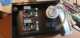
I'm struggling with finding shelf space for dual enclosures. Any suggestions on how to include both the power supply and the dual Emeralds in the same enclosure? Best practices I should be aware of?
I'm using this one:
BZ3207P Full Aluminum Enclosure /chassis / preamp case/ amp box 320*70*248mm | eBay
Nice quality and plenty of space. I'm using additional power supply boards.
BZ3207P Full Aluminum Enclosure /chassis / preamp case/ amp box 320*70*248mm | eBay
Nice quality and plenty of space. I'm using additional power supply boards.
I'm using this one, must complete it 🙂
need some screening between transformer and emerald units.
Audiophile Aluminum Enclosure Power Amplifier/Preamp/DAC Chassis DIY Case House 9639051624852 | eBay
not cheap tho
£58
need some screening between transformer and emerald units.
Audiophile Aluminum Enclosure Power Amplifier/Preamp/DAC Chassis DIY Case House 9639051624852 | eBay
not cheap tho
£58
Attachments
That's about the price you can expect for that kind of chassis. They conveniently come with the IEC socket/fuse and preformed cutout for it, and are easy to work with.
Do note that you'll need to sand off the black coating at the panel joins and at the ground lug so as to make the electrical connectivity needed for good shielding.
Do note that you'll need to sand off the black coating at the panel joins and at the ground lug so as to make the electrical connectivity needed for good shielding.
I don't see many reports on op-amp options. OP27 is standard, OP37 is an option, and one person has built with LME47910 but no comparisons etc.
I've been really enjoying the Emerald, and have some C3 experiments yet to go. Anyone got any recommendations for the opamps? No point in recommending something unobtainium or crazy exotic. I'm talking standard stuff available from Farnell etc. I have some adaptor boards so SOIC would be ok too.
I've been really enjoying the Emerald, and have some C3 experiments yet to go. Anyone got any recommendations for the opamps? No point in recommending something unobtainium or crazy exotic. I'm talking standard stuff available from Farnell etc. I have some adaptor boards so SOIC would be ok too.
Previous listening evaluations by myself and Keith Marshall suggested the OP27 remains the best option for the Emerald, as it was for the Phonoclone.
Different op amps certainly do lend a different sound, so I do recommend swapping out a few to try, but don't be surprised if you come back to the OP27 at the end. It's a really clean, smooth, and neutral IC.
Different op amps certainly do lend a different sound, so I do recommend swapping out a few to try, but don't be surprised if you come back to the OP27 at the end. It's a really clean, smooth, and neutral IC.
Can i use 1/10W (Vishay RN55) resistor for R7.
https://eu.mouser.com/ProductDetail...kEX%2brfy3Q==&countrycode=DE¤cycode=EUR
I have some in my stock. The BOM suggest 1/4w.
https://eu.mouser.com/ProductDetail...kEX%2brfy3Q==&countrycode=DE¤cycode=EUR
I have some in my stock. The BOM suggest 1/4w.
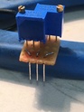
I had a discussion with Richard a short time ago about differing voltage readings between the two phono boards after the regulators. Richard told me it was down to the matching of the pnp to npn devices. Richard explained to me how to do this and I did try to match them but in the end I had to find an easier method of achieving consistent voltage readings across both boards. Richard suggested playing around with the values of R20/R21 but I found that a bit labourious. After some reading up I came up with another solution. I removed the trimmer R21 and replaced it with a pair of 1K trimmers either side of the 0V rail which gives independent control of the + and - rail.
Circuit diagram here;
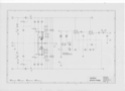
I made up two small circuit boards with trimmers installed that would fit in the three holes for the original single trimmer;
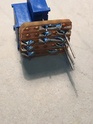
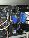
With a 12v-0-12v transformer I can adjust either rail to well over 16 volts;
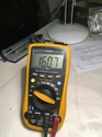
Right now I have each rail set at 14 volts and the phono stage is performing well. I'm going to leave the phono stage on soak for a while and if all goes well I'll mod my single box phono stage.
Circuit diagram here;
I made up two small circuit boards with trimmers installed that would fit in the three holes for the original single trimmer;
With a 12v-0-12v transformer I can adjust either rail to well over 16 volts;
Right now I have each rail set at 14 volts and the phono stage is performing well. I'm going to leave the phono stage on soak for a while and if all goes well I'll mod my single box phono stage.
Now you adjust one of the rails to 13.5 V to test if you can hear any difference!
I'll try that Richard. Funnily enough I now have both rails set at 13.5 volts and I'm happy.
Making the outputs independently variable is an interesting opportunity to check what is and what isn't audible. You can change the output of both sides equally, so the difference between 10 and 14 V, say, and you can change just one side to see how much imbalance is needed before the sound is affected.
I could change the original Emerald board to use two potentiometers easily enough, if it is needed. Note though that adjusting the gain to match the voltages means that the dynamic properties of the voltage regulator (gain, feedback, noise, ripple rejection) are now unbalanced between the positive and negative rails, even if the static properties (the DC output) are close.
In my view it's better to match dynamic rather than static parameters in audio, since the signal itself 20-20kHz, rather than DC.
[edit: though, yes, the single pot. already implemented imbalances the dynamic amplification to an extent, it's true...]
I could change the original Emerald board to use two potentiometers easily enough, if it is needed. Note though that adjusting the gain to match the voltages means that the dynamic properties of the voltage regulator (gain, feedback, noise, ripple rejection) are now unbalanced between the positive and negative rails, even if the static properties (the DC output) are close.
Surely the aim must be to supply both rails of the active circuit with the correct voltage. Because the transistors in each regulator can't be sufficiently well matched both in pairs and board to board we can end up with each board running at slightly different voltages. As you know in one build I had a one volt difference in regulated voltage between boards. With a single trim pot across both voltage regulators it's only possible to equalise the rail voltage on each board. When I look at the circuit diagram I actually see two regulators, one for each rail and I can't see any reason why each regulator shouldn't be independently controlled.
Richard, does the gain of the Emerald change with a change in supply voltage?
- Home
- Source & Line
- Analogue Source
- RJM Audio Emerald Phono Stage Help Desk