Good morning,
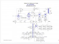
I would have some question about an amplifier with 845 tubes on behalf a person who I know, that doesn't work properly. In the case the main problem seems to be in the PSU since I observed having just one 5R4 in the first side of the schematic (for the 845 B+ supply) and this goes over the max V, from specs, even for the proper C(in).
In fact, the other consequent problem is the overheating of the transformer (it reaches up to 80-90 ° measured), which has probably led to "cooking" it.
The other doubt, is the OT with primary impedance of 3.5K wich is supposedly too low for a pair of these power tubes and leads to some distortion.
Now, since this job is quite out of my reach I wondered an opinion in order to solve the more importants problems, then any finishing touches are left in the following times.
Upon hearing from another manufacturer in the area, he proposed a different approach using some EF86 as preamps and drivers (yes, both if I remember correctly). This seems to me an odd solution whith 845, but I don't know....I read of an amp running with 4 small 12AX7 - two for channel for each 845 - the Orfeo "Bel Canto" and it is a good sounding amp. How about it then?
The owner is very disheartened as he spent a lot of money on a device he relied on and then it turned out to be a rip off, now he wants to to fix things but without spending a fortune, possibly without upset the project.
Attachments

Not an expert but I think the schematic design and load are acceptable in fact quite nice. I am sure you could have a custom winder make you a much bigger power trans which would improve everything provided they could fit it on the chassis and there is no nasty surprises like filament bridges potted in with the power trans..
Are you sure there isn’t something shorted out? That would definitely cause the transformer to overheat. Check all the voltages and see if anything is out of spec. The opt impedance seems fine for two 845.
It may be so indeed. I have not close at hands the amplifier (the owner lives in another town) and he has no suitable instuments to measure the voltages. However, his idea is to get another transformer for B+ (plates, etc) and a toroidal one for filaments even put in another external chassis.
Did the amp ever function correctly? Even a cheap digital meter would be a valuable investment to understand what is happening. Blindly replacing parts is foolish imho when the problem could be a $1 part.
What I would do:
1. Disconnect one end of each transformer winding. Measure the AC voltage on each one to check that they are good. Measure the impedance between each winding to check for shorts.
2. Put a pair of 12V SMPS turned down all the way to heat each 845. That will take some MAJOR stress off the power transformer.
3. AC heat the driver tubes. DC heating here is a total waste of transformer VA, especially since you have a feedback network.
4. Bypass the 5R4 with some very high voltage SS diodes.
5. Post some build photos here. In particular, we can look at the size of the OT with respect to the 845 to assess if it's sufficient for the job. The 3.5K load for paralleled tubes is fine.
Are you sure there isn’t something shorted out? That would definitely cause the transformer to overheat. Check all the voltages and see if anything is out of spec. The opt impedance seems fine for two 845.
Did the amp ever function correctly? Even a cheap digital meter would be a valuable investment to understand what is happening. Blindly replacing parts is foolish imho when the problem could be a $1 part.
He called me, and said they were measured. At the input of the OT primary is a less above 900V, while it should be at least 200V more. It's clear that the main problem is the power transformer , as me too supposed, to be faulty. Current at each 845 is ok, with 70mA when full operation
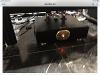
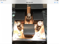
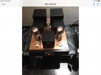
It's probably a good idea to at least take the covers off the shrouds and photograph what's inside.
The 5R4 specs call for 575 Ohms of primary DCR for a 4uF cap input filter.
You have 7.5uF cap input filter (two 15uF in series).
Check the DCR of the secondary.
The 5R4 PRV rating is 2700V (depending on other conditions).
With the amp in a No load condition (like the 845s not warm, the PRV is 2687 minus the rectifier drop.
And at 93mA per 845, as well as the 13mA for the driver, you are exceeding the current and max PRV combination specs of the rectifier.
Check the ratings of the Exact 5R4 tube you have, 5R4, 5R4G, etc.
This seems like an attempt to really push the parts hard, to and or beyond their specified limits.
Last edited:
If the person you know can do with a little less power, then try the following:
The B+ voltage will be reduced a lot.
You might be able to use a small input capacitance, that will reduce the peak currents ('I'squared x DCR heating of the secondary).
Perhaps a 1uF of capacitor, or two 2uF caps in series to get the voltage rating you need.
The tradeoff will be much less transformer heating, versus the lower B+ voltage.
The 845 (not 211) plate resistance is 1700 Ohms, for two 845 in parallel, that is 850 Ohms. 3,500 / 850 = about 4. A damping factor of 4 is fine for a triode output that is not using global negative feedback. Each 845 "sees" 7k Ohms load.
You will have to reduce the reistance of the self bias resistors on the 845 tubes, to get the current back up to 70mA, or whatever value is needed.
This is a simple thing to try, and inexpensive too.
The power out will be less, but the amp will run much longer, and the fire truck will be less likely to ever have to come to his home.
Last edited:
At the input of the OT primary is a less above 900V, while it should be at least 200V more. It's clear that the main problem is the power transformer , as me too supposed, to be faulty. Current at each 845 is ok, with 70mA when full operation
So V(ak) is 800v or so with 70ma. This seems to be a good operating point for your 6k OT (3k x 2).
Unfortunely I haven't here at hand the amplifier otherwise I could check it out (change in input capacitor, cathode resistor etc.). The owner is a little busy now so I can't move, and disappointed up that would set aside everything. I incouraged not to do it, but he will decide.
As for the rectifier tube, all 845 psu I've seen usually has a couple of 5R4 or better a mercury vapour tube. Yes a single 5R4 is pushed to work "hard" on the PIV. Besides he doesn't want any diode just tubes.
I conseiled him then to contact a serious builder in his area...
As for the rectifier tube, all 845 psu I've seen usually has a couple of 5R4 or better a mercury vapour tube. Yes a single 5R4 is pushed to work "hard" on the PIV. Besides he doesn't want any diode just tubes.
I conseiled him then to contact a serious builder in his area...
Adding a 2nd rectifier makes it easier on the rectifiers.
But there will be less voltage drop across the rectifier(s), and that will make the heating on the B+ secondary even worse.
Plus there needs to be another 5V transformer to run the 2nd rectifier filament.
Real modification requires real work.
It is easier to start from scratch with a good design, and conservative ratings on parts etc.
That's right and more easy for the 5Z4.But this seems to be allready the case and still a hot transformer 🙁So V(ak) is 800v or so with 70ma. This seems to be a good operating point for your 6k OT (3k x 2).
The schematic has a 3k OPT and the TS is saying 3k5 (@#1), makes no big difference.
Mona
Attachments
That's right and more easy for the 5Z4.But this seems to be allready the case and still a hot transformer 🙁
The schematic has a 3k OPT and the TS is saying 3k5 (@#1), makes no big difference.
Mona
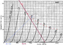
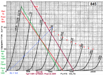
Just on going down with V(B+) I read that for Shuguang 845 tube (the owner of the amp has these ones) an option is 750V/70mA, so could be ok this graph?
Attachments
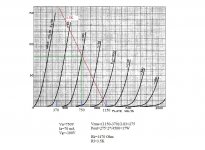
Confusions confusions 😱Just on going down with V(B+) I read that for Shuguang 845 tube (the owner of the amp has these ones) an option is 750V/70mA, so could be ok this graph?
Schematic Ra=3k , you say 3k5 and the last graph is with 4k5 ???
What you have is the green or red loadline post #16.
Mona
May I ask if the owner is overall happy with the sound? You mentioned distortion with the current OT but maybe this is just perception?
The hot PT is a concern but surely it's condition could be checked. Also there is concern with the tube rectifier. For piece of mind series diodes could be installed between it and the transformer to prevent damage. This is what I did with my 845.
I am a hobbyist and not an expert but the amp seems to be well thought out.
- Home
- Amplifiers
- Tubes / Valves
- Problem with Audiodarex SE 845