Confusions confusions 😱
Schematic Ra=3k , you say 3k5 and the last graph is with 4k5 ???
What you have is the green or red loadline post #16.
Mona
Sorry, that wasn't the AC loadline...yes I confirm 3.5K, the builder wrote 3K but in reality it's the first one.
May I ask if the owner is overall happy with the sound? You mentioned distortion with the current OT but maybe this is just perception?
The hot PT is a concern but surely it's condition could be checked. Also there is concern with the tube rectifier. For piece of mind series diodes could be installed between it and the transformer to prevent damage. This is what I did with my 845.
I am a hobbyist and not an expert but the amp seems to be well thought out.
You mean a circuit like this?
Anyway, the question should be made to him because I never listened it. As he referred to me it doesn't sound bad apart that 10-20min after powerup the transformer turns really hot, and the 5R4 over-glowing
Attachments
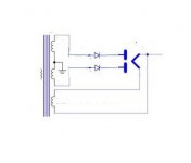
You mean a circuit like this?
Yes that is what I was thinking of. Diode selection will not be trivial due to high voltage requirements. In my case it is a hybrid bridge so 1500V SiC diodes are ok.
1/2 secondary 950V x 1.414 = 1343V peak
7.5 uF at 100Hz full wave rectification = 212 Ohms capacitive reactance.
0.070A x 2 = 0.14A. Two 845 tubes current
0.14A x 212 Ohms = 29.7V peak to peak ripple.
29.7V peak to peak, versus 1343V peak means the current peaks are very large into the 7.5uF capacitor.
The time of charging the 7.5uF capacitance is a very small portion of the 1343V alternation.
So, the ((Peak Current)squared) x DCR of 1/2 secondary squared = Lots of Watts.
That causes a very hot secondary.
The Key words are current SQUARED.
All the above are just some facts, combined with just my opinion.
Last edited:
When a silicon diode is in series with 1/2 of a tube rectifier, one of them has more reverse leakage current than the other.
The one with the lower leakage current as the Most reverse voltage across it (Usually the tube rectifier).
The one with the higher leakage current has the Least reverse voltage across it (Usually the silicon diode).
Your mileage may vary.
The one with the lower leakage current as the Most reverse voltage across it (Usually the tube rectifier).
The one with the higher leakage current has the Least reverse voltage across it (Usually the silicon diode).
Your mileage may vary.
I really don't understand this trend of putting diodes ahead of the tube. The 5R4 is fast heating so your only advantage now is the voltage drop.
astouffer,
Some think you can double the PIV rating that way.
(2000V PIV rectifier, and 2000 PIV solid state diode, total PIV may, or may not, = 4000V).
When it works, it works.
When it does not work, it does not work.
Their mileage may vary.
ZZZap!
Some think you can double the PIV rating that way.
(2000V PIV rectifier, and 2000 PIV solid state diode, total PIV may, or may not, = 4000V).
When it works, it works.
When it does not work, it does not work.
Their mileage may vary.
ZZZap!
As I understand it the worst case scenario is the tube rectifier failing shorted therefore the SS diodes should be rated for full current and PIV.Some think you can double the PIV rating that way.
(2000V PIV rectifier, and 2000 PIV solid state diode, total PIV may, or may not, = 4000V).
In reference to the amp discussed in this thread; the SS diodes take some of the load extending the life of the tube rectifier while retaining it's aesthetics, voltage drop and slow warmup (and sound quality in my opinion).
I will not pretend that I fully understand the mechanism by which the series SS diode tweak works. What I do know is that it DOES work. Installing the tweak in units whose Sovtek and JJ 5AR4s arced made short shrift of "fireworks" display. 
FWIW, 1 fellow surmised that some sort of Zener/avalanche effect was occurring.
In this wickedly high PIV situation, I'm thinking 3X series wired UF4007s, along with voltage equalizing resistors, be installed between the rectifier winding and the 5R4's plates.
FWIW, 1 fellow surmised that some sort of Zener/avalanche effect was occurring.
In this wickedly high PIV situation, I'm thinking 3X series wired UF4007s, along with voltage equalizing resistors, be installed between the rectifier winding and the 5R4's plates.
Attachments
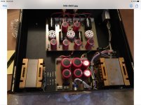
They look like really nicely built amps. It's a interesting idea putting the driver stages offboard that I never thought off. It might be something quite simple to fix. At those voltages even new parts fail like caps leaking. He could swap the valves left to right and see if the heating changed sides though just getting a tech to fix them could save a burnt out power trans which is looking likely if he keeps running them.
They look like really nicely built amps. It's a interesting idea putting the driver stages offboard that I never thought off. It might be something quite simple to fix. At those voltages even new parts fail like caps leaking. He could swap the valves left to right and see if the heating changed sides though just getting a tech to fix them could save a burnt out power trans which is looking likely if he keeps running them.
Yes, before he showed me the images of the amplifier actually I didn't know anything about this italian builder. In practice, he makes Audionote replicas.
Far from being constructively identical (and I guess it takes!) but aestetically seem really clones: he put his own logo even with their intials same as Audionote...
I'm trying to encourage the owner not to throw the money away with a not well qualified repairman and just try and see though the suggested tweaks before. If I lived near him I could check it by myself...
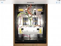
This evening I got the images from him of the interior of both sections (preamp/driver and final).
He told me some concerns about the lack of evident components in the finale, as I noticed me too.
It actually looks a bit sparse but I have an idea that part may be hidden by the rectangular panel.
He told me some concerns about the lack of evident components in the finale, as I noticed me too.
It actually looks a bit sparse but I have an idea that part may be hidden by the rectangular panel.
Attachments
- Home
- Amplifiers
- Tubes / Valves
- Problem with Audiodarex SE 845