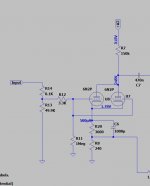
Hello, I'm tesing a common chatode resistor of around 3-4 kohm with 500uA current (250uA bias per tube) and I like the sound in my parallel configuration.
Measured distortion is not so bad, but I'm using heavy GNFB and the resistor is bypassed by a cap.
I have 315V++ with 150Kohm common plate resistor. Plate voltage is 245V.
I don't see schematics with such low bias (even with just one tube and 6-8K cathode resistor), and I'm looking for similar solutions and possible issues.
Thanks
Is the negative grid voltage in part created by gridcurrent biasing? What is the value of the grid resistor?
I ask this because with a 4K cathode resistor passing 0.5 mA you would get Vk = 2 V (or Vg = - 2 V). Looking at the datasheet for the ECC83 (and the curves for the 6N2) one section would pass about 1 mA at Va = 245 V and Vg = - 2 V , so the two sections would pass about 2 mA instead of 0.5 mA.
I ask this because with a 4K cathode resistor passing 0.5 mA you would get Vk = 2 V (or Vg = - 2 V). Looking at the datasheet for the ECC83 (and the curves for the 6N2) one section would pass about 1 mA at Va = 245 V and Vg = - 2 V , so the two sections would pass about 2 mA instead of 0.5 mA.
Hi, the cathode resistor is common to the two parallel tubes.
So in 4kohm there is about 0.5mA and about 2V drop, sourced by the two tubes, thus 0.25mA bias each as they are in parallel.
So in 4kohm there is about 0.5mA and about 2V drop, sourced by the two tubes, thus 0.25mA bias each as they are in parallel.
But at a plate voltage of 245 V and with Vg being - 2 V, it's not possible that one section only passes 0.25 mA unless the tube under test is very duf (both sections) or unless there is additional biasing going on (so to get Vg more negative than - 2 V).
OK, than your tube under test seems to contradict its datasheets...
Addition: Here's a datasheet for the 6N2. Look at what current one section will pass at Vplate = 243 V and Vg = - 1.78 V.
Addition: Here's a datasheet for the 6N2. Look at what current one section will pass at Vplate = 243 V and Vg = - 1.78 V.
Attachments
Last edited:
ygg-it,
You have connected the plates together.
You have connected the cathodes together.
You have connected the grids together.
If you have any oscillations, try a couple of individual grid stoppers in the grids.
And I hope the plate currents are roughly equal. Otherwise the distortion may be a little bit high.
Only way to tell are with precision small value resistors in the plates, or or small value resistors in the cathodes
(I prefer the current sense resistors to be in the plate circuit, the same value of resistance will not disturb the circuit performance).
Measure the voltage across the resistors with a sensitive DMM, to check the current balance. If the current balance is bad, try another tube.
Last edited:
OK, than your tube under test seems to contradict its datasheets...
Addition: Here's a datasheet for the 6N2. Look at what current one section will pass at Vplate = 243 V and Vg = - 1.78 V.
Ok I have done measurements and may be plate voltage is little less than simulation, but the cathode current is really 0.5mA-0.6mA split in two, so each tube is really biased "cold" at 250-300uA, as simulation states.
So question stay the same: why I don't see schematics with such low bias current, i.e. with very large cathode resistors (some Kohms), since they sound pretty good and give me much higher input headroom?
So question stay the same: why I don't see schematics with such low bias current, i.e. with very large cathode resistors (some Kohms), since they sound pretty good and give me much higher input headroom?
The answer may be quite simple. They tend to follow the recommendations in the data-sheets of - e.g. - ECC83 from philips.
For 1mA plate current, THDistortion is given as 1.1%
at 0.36mA, THD quadruples and reaches 4.6%
Thats for one triode.
If you like your setup, well, thats your personal choice. Most others opt for lower distortion, as it seems.
Attachments

Ok I have done measurements and may be plate voltage is little less than simulation, but the cathode current is really 0.5mA-0.6mA split in two, so each tube is really biased "cold" at 250-300uA, as simulation states.
So now there's 0.6 mA passing through the common anode resistor of 150K. That gives a voltage drop of 90 V.
The voltage drop over the common cathode resistor now is 0.0006 x 3840 = 2.3 V.
Your B+ = 315 V, so the voltage between the cathodes and the plates = 315 - (90 + 2.3) = 222.7 V.
Looking at the curves in the datasheets, one section passes about 0.5 mA at Vplate = 222.7 V and Vg = - 2.3 V, so the two sections together would pass about 1 mA at this Va and Vg.
So I'm still having a hard time to understand how your simulations and/or measurements are possible.
The answer may be quite simple. They tend to follow the recommendations in the data-sheets of - e.g. - ECC83 from philips.
For 1mA plate current, THDistortion is given as 1.1%
at 0.36mA, THD quadruples and reaches 4.6%
Thats for one triode.
If you like your setup, well, thats your personal choice. Most others opt for lower distortion, as it seems.
Interensting table thanks! But I think that with heavy GNFB which I'm using, this is not valid anymore. Strange infact that rising the cathode resistor I'm getting less or almost equivalent overall THD (measured)!
Oh,
Negative feedback covers over lots of intrinsic distortion.
Make the intrinsic distortion lower in the first place, before appling negative feedback,
and you will see even less distortion than before.
Negative feedback covers over lots of intrinsic distortion.
Make the intrinsic distortion lower in the first place, before appling negative feedback,
and you will see even less distortion than before.
ygg-it,
funny, I use that exact configuration (paralleled 12AX7, cold bias) to emulate the sound of an heavily overdriven old sixties guitar power amp, and actually is the best emulation of that specific sound that I've ever found.
funny, I use that exact configuration (paralleled 12AX7, cold bias) to emulate the sound of an heavily overdriven old sixties guitar power amp, and actually is the best emulation of that specific sound that I've ever found.
Perhaps the doubling of the Miller capacitance makes it sound so good to you.
To me it is weird that on a diy forum we are discussing a particular circuit with values that are simply impossible according to Ohm's Law and datasheets.
But we all live in strange times anyway, with alternative facts and all...
To me it is weird that on a diy forum we are discussing a particular circuit with values that are simply impossible according to Ohm's Law and datasheets.
But we all live in strange times anyway, with alternative facts and all...
Are we talking about Hi Fi tube amps?
Are we talking about Guitar tube amps?
Or are we talking about Both?
Are we talking about Guitar tube amps?
Or are we talking about Both?
To me it is weird that on a diy forum we are discussing a particular circuit with values that are simply impossible according to Ohm's Law and datasheets.
My apologies,
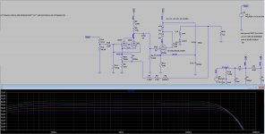
 you were right! I had an hidden DC voltage at the input signal which biased the triodes in absence of the DC-block cap.
Now the correct simulation mirrors my voltage measurements like a "swiss clock".
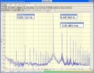
On 8ohm resistor load:
Measured THD
0,28% THD = 1W
1% THD = 3,9W
5% THD = 5,5W
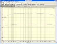
Meas freq response (with PC soundcard and Digital wav files).
20Hz (-0.8dB)..20KHz (-0.4dB) with full GNFB in pink colour
IMD 60-7KHz: 0.25%
Attachments


Last edited:
ygg-it,
funny, I use that exact configuration (paralleled 12AX7, cold bias) to emulate the sound of an heavily overdriven old sixties guitar power amp, and actually is the best emulation of that specific sound that I've ever found.
Thanks for this your experience.
I know... and unfortunately the only schematics I found using "cold bias" were just for guitar overdrive, called "cold clipper"...
Overdrive
Last edited:
Are we talking about Hi Fi tube amps?
Are we talking about Guitar tube amps?
Or are we talking about Both?
Hi Fi, of course
- Home
- Amplifiers
- Tubes / Valves
- Parallel 6N2 ECC83 12AX7 cold bias: how much is used??