Note that this requires a 12V 0.8A AC power supply
Hi thanks ! a transformer then ... no problem at all
I will buy one. But i guess the real issue is the power supply for the plates
The schema looks good ... but i am not an expert
Attachments
Sometimes trying to make things "simple" ends up making them needlessly complicated. What´s wrong with building a real tube buffer/preamp, fed real voltages from a real power supply? Which to boot will work 10 times better
You are perfectly right ... personally i like a board with the parts value printed on it Like the kit i have seen
Sorry ... when you say 10 time better ... what you mean ? less noise and distortion ?
From the pictures in post #11 I can make out that there is a load resistor of 4K7 and that the cathode resistor is 220 Ohm. So it is indeed more a preamp than a 'true' buffer ...
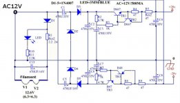
Hi i understand that this power supply (ref. post 21) of the Fever design is less than optimal
Are you thinking of any mods maybe ? like increasing C2 and C6 value to 2200uF ?
Last edited:
I can't help you with that because my knowledge of semi-conductors is very limited. Beside diodes, the occasional zener, and LM317's for feeding the filaments of low-level stages (phono preamplifiers), I don't use semi-conductors in my projects. Furthermore I never use voltage doublers (I prefer to use the right transformer for the job).
I agree with JMFahey on this one: What's wrong with keeping it simple? But it's your project ofcourse.
I agree with JMFahey on this one: What's wrong with keeping it simple? But it's your project ofcourse.
I can't help you with that because my knowledge of semi-conductors is very limited. Beside diodes, the occasional zener, and LM317's for feeding the filaments of low-level stages (phono preamplifiers), I don't use semi-conductors in my projects. Furthermore I never use voltage doublers (I prefer to use the right transformer for the job).
I agree with JMFahey on this one: What's wrong with keeping it simple? But it's your project ofcourse
Hi ! i am trying to understand what is wrong with the Fever power supply design just that. I like it a lot. But i have got opinions that say that the FX audio is the better unit. It uses what looks like a dc-dc converter to generate the plate voltage.
Of course i like very much to keep things as simple as possible.
I like the idea to try to mod something ... but i understand that most people here prefer to develop their own design from the scratch and modding does not stimulate their interest.
No problem ... i will look around for modders like me

Thank you very much for the schematic. Kind regards, gino
Last edited:
You are perfectly right ... personally i like a board with the parts value printed on it Like the kit i have seen
Sorry ... when you say 10 time better ... what you mean ? less noise and distortion ?
I can't speak for the other posters but it seems like they're saying the same thing I did earlier.Hi ! i am trying to understand what is wrong with the Fever power supply design just that. I like it a lot. But i have got opinions that say that the FX audio is the better unit.
I don't know enough about these types of power supplies to be able to say which one is technically better. From what I see, the Fever uses an AC input, the FX uses a DC input but, in the end, they both send the same, ridiculously low, voltages to the tubes.
So, as I see it, it really doesn't matter which of these power supplies you use because neither one of them provides sufficient voltage to the tubes. The limiting factor is the operating point of the tubes.
We have a saying here, and perhaps there is an Italian equivalent. "You can put lipstick on a pig, but it's still a pig."
In other words, whatever power supply design you choose, whatever upgraded parts you put in, if the tubes are being operated at the same ridiculously low voltages, there will be no significant difference in the sound.
I'm not saying that modding the circuit you've got won't improve the sound at all. I'm saying that those improvements will be relatively minor. Any alternative that uses a tube correctly will sound much, much better.
I say that based on my experience breadboarding this tube with both the (low) stock voltages and "normal" voltages. The sound improved dramatically when the tube was operated as it was intended to. And, frankly, numerous other tube types that I tried (at normal voltages) sounded better to me.
I don't mean to be harsh. I just hate to see someone spend time, money and effort and get so little in return. It's just as easy to put something together that works much better.
The guys who are spending many times the initial cost of the FX on tube rolling, linear power supplies and various other mods have never heard the tube being run at "normal" voltages. If they did they would immediately wonder why they've spent so much on "lipstick".
@JMFahey says "What´s wrong with building a real tube buffer/preamp, fed real voltages from a real power supply?"
He is suggesting that you build something using a traditional power supply (a transformer that operates on wall voltage, followed by some combination of caps, resistors and possibly inductors) that produces the voltages that the tube is designed to use.
The simple fact is that operating a tube using the correct voltages will always sound much better than trying to use the same tube at incorrect voltages.
I assume that's what he meant when he said "10 times better".
I'd suggest building something on a breadboard first. It will give you plenty of room to work and everything can be hooked up with no soldering required. You can try different circuit designs just by moving a few things around. With a circuit board you're stuck with that design.
But if you insist on building using a circuit board there are plenty of them out there. Start by reading the datasheet for whatever tubes they use. Then make sure that the board is designed to run the tubes at "normal" voltages. You'll probably find lots boards that use common tubes like the 12AX7, 12AU7, 12AT7 and maybe some others.
The end result will be much better.
Or, if you're hell-bent on using ultra-low voltages, there are tubes that are designed specifically for that. They are called "space charge" tubes. Do some research or start a new thread about using them in a preamp. They are the right tool for the job in a low voltage situation. That's the key, use the right tool for the job. There may not be any circuit boards available for them though.
Hi ! thanks a lot ! for now i have already ordered a stock of 6Ж1П from Ukraine.
Anyway i wonder if the 6Ж38П is completely equivalent electrically to the stock tube. I would not want to stress the unit.
I see many on ebay ... is there a specific brand/source to look for ?
https://www.ebay.it/sch/i.html?_from=R40&_nkw=6J38P&_sacat=0&rt=nc&LH_BIN=1
prices are very good indeed ... no more than 2USD/each shipping included
6Ж38П is like 6Ж1П with higher transconductance. With common cathode you can get higher gain with the same load resistance, in cathode follower you will get lower output impedance.
I can't speak for the other posters but it seems like they're saying the same thing I did earlier... So, as I see it, it really doesn't matter which of these power supplies you use because neither one of them provides sufficient voltage to the tubes. The limiting factor is the operating point of the tubes ....
thank you sincerely for the kind and useful information. I think one reason i was attracted by these devices is because of their low voltages. Voltages normally found in tubes are high and lethal. Considering my absolute lack of competence the risk becomes high.
If I started from a kit I think with clear instructions or at least the diagram and a board with the components names engraved on the pcb I believe that the risk would be less because I could draw on the board the path of the high voltage with a red marker for instance.
So now my question is whether to take a tube kit or just drop the tubes and go back to the transistors.
I'm only interested in the preamps or buffers.

As for the power amp I think I really can find a solution much more easily. Actually i have already one that i like very much indeed.
Although these 6J1 based preamps i understand now are limited by design I really like the tone they provide to the overall sound. In everything ... both in music and in watching movies.
They seem to relax the sound in a very musical way.
The flaws I feel are an incomplete transparency and perhaps a lack of dynamics on the mid-bass which is good but pushes little for instance in drums tracks. The sound comes out less from the speakers.
I didn't understand then if the use of the pentode as a triode is a good choice. For sure is not that common. Usually the preamps all use triodes But I've always wondered if other tubes could give even more performance.
Then speaking of buffers ... are all the tubes fine the same or are there ones better for the purpose ?
if I'm not mistaken my friend's preamp uses a 12au7 as a buffer / line stage
We compared it to my solid state pre and while the midrange of his was much more musical on the bass there was no history, the solid state bass was better. Even he who loved deeply his preamp was a bit perplexed. However, the idea is to use a 12bh7 that I respect. I really do not know why nobody cares about it.
So since there is absolutely no project around and I am not able to calculate anything I will look for a kit for 12 au7 and I will put a 12bh7 in it and check that the power supply is adequate ... at least for the heater. If it doesn't go well, I'll let it go. I am not able to start from scratch ... I would only make disasters and risk my skin as well.
Thanks again for your kind and valuable advice.
Kind regards, gino
6Ж38П is like 6Ж1П with higher transconductance. With common cathode you can get higher gain with the same load resistance, in cathode follower you will get lower output impedance.
Hi thank you very much for your kind and helpful advice. Unfortunately I understand now that the unit i am using is flawed by design. And that the tube itself has limits compared to more common triodes.
Kind regards, gino
Hi ! anyway ... i would not underestimate what an upgrade of key passive parts can provide to the sound. Sometime i read comments like this one ... i tend to believe to them
without fixing on the Jantzen Superiors ... my guess is that the parts used in these cheap units HAVE to be very very low in quality. A decent MKP would not cost a fortune and maybe increase transparency a little more.
That "sounds 10 times better" still rings in my mind. I have looked everywhere but found no measurements of noise or distortion. That would be a good point to start further discussion. Maybe a "better" sound is mirrored by better measurements ? assuming that tube distortion is a good thing ... i am sure noise is never a good thing. Never.
...And while I was at it I upgraded the capacitor to Jantzen Superior Z-Cap. I was way below the budget I had planned, so spending another $40 on the capacitor upgrade was no problem even though the capacitors cost more than the preamp kit. I have never tried Jantzen caps before so I didn't know what to expect or had no expectations on drastic sound improvement. OMG! Was my expectations wrong. I couldn't believe my ears of what I was hearing: the clarity, sound stage, every little details, and nuance. It also smoothed the edgy sound and it was so silky smooth. I didn't know changing the cheap Chinese capacitors with the high quality European capacitor would have this much of impact on the sound quality....
without fixing on the Jantzen Superiors ... my guess is that the parts used in these cheap units HAVE to be very very low in quality. A decent MKP would not cost a fortune and maybe increase transparency a little more.
That "sounds 10 times better" still rings in my mind. I have looked everywhere but found no measurements of noise or distortion. That would be a good point to start further discussion. Maybe a "better" sound is mirrored by better measurements ? assuming that tube distortion is a good thing ... i am sure noise is never a good thing. Never.
Last edited:
Sorry ... when you say 10 time better ... what you mean ? less noise and distortion ?
Tubes workk better, at least properly, with high voltages, think 160V to 250V, just look at datasheet examples and suggestions, with some offering borderline performance at 90V (because when they were designed there was some equipment working out of 110V DC lines).
So a complicated circuit to get +/-28V will still be much worse than a simple transformer winding supplying, say, 150 t0 250VAC plus a simple diode (at least) and proper high voltage capacitor.
Except for some double triodes (like ECC84/PCC84 and ECC88/PCC88) that were designed for cascode operation in the first stage of TV's. They are happy with about 90 V between cathode and plate.
But a warning: These tube types were designed for HF applications. Especially the ECC88/PCC88 has a high mutual conductance (12.5 mA/V) and is prone to oscillate unless you know what you're doing. So if you want to use a double triode like this, I would advise the ECC84/PCC84 (mu = 24, S = 6 mA/V).
But a warning: These tube types were designed for HF applications. Especially the ECC88/PCC88 has a high mutual conductance (12.5 mA/V) and is prone to oscillate unless you know what you're doing. So if you want to use a double triode like this, I would advise the ECC84/PCC84 (mu = 24, S = 6 mA/V).
Tubes workk better, at least properly, with high voltages, think 160V to 250V, just look at datasheet examples and suggestions, with some offering borderline performance at 90V (because when they were designed there was some equipment working out of 110V DC lines).
So a complicated circuit to get +/-28V will still be much worse than a simple transformer winding supplying, say, 150 t0 250VAC plus a simple diode (at least) and proper high voltage capacitor.
 but the preamp circuit could be kept unchanged ? i mean the resistors values ... i will not be able to recalculate all the resistors in it If i have to recalculate the preamp circuit i will have to pass ...
 a higher voltage power supply that i can work it out with some attention to the risks. For instance there are dc-dc step-up converter going up to 300VDC and more ... variable
But also i could use PS kit intended for projects with other tubes
Last edited:
I'm not sure why you're concerned about keeping the same resistor values. If you're going to order different caps it's just as simple to order different value resistors, if that's what is needed.
a higher voltage power supply that i can work it out with some attention to the risks. For instance there are dc-dc step-up converter going up to 300VDC and more ... variable
But also i could use PS kit intended for projects with other tubes
Again, it's good that you realize that high voltages can be deadly but if you just use common sense you'll be fine.
I believe the wall voltage in Italy is 220vac, right? If you measure it might even be higher since it fluctuates during the day. You've got high voltage inside all of your household appliances and, presumably, you have enough sense not to go sticking your fingers inside them when they are plugged in and turned on.
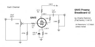
There are plenty of schematics out there that are simple. No need to calculate or design anything from scratch. The stuff I build is mostly copy and paste. I posted two schematics over at AK. I've attached one of them. I used a bench power supply so this is only the audio portion. Each channel uses: six resistors, two film caps, one electrolytic cap, one volume pot and two RCA jacks. Super simple.
I'm not necessarily suggesting that you use this, just posting it as an example of simplicity. I just threw it together to get an idea of what this tube sounded like with more "normal" voltages. A true buffer using this tube, a 12AU7 or a 12BH7 or whatever, will not be much different.
Breadboarding a design allows you to change things around easily. Sockets like these use screw connectors, no soldering needed.
7-pin mini breadboard / prototype tube socket for DIY experimenting | eBay
9-Pin Socketed Vacuum Tube Breakout Board (NEW) | eBay
To connect parts, use Fahnestock clips or various types of terminal blocks that use screws to attach parts. Other types of connectors and breadboards that use plug in terminals may not be suitable for higher voltage tube circuits. Clip leads allow you to connect parts together, no soldering needed.
Attachments
Last edited:
I'm not sure why you're concerned about keeping the same resistor values. If you're going to order different caps it's just as simple to order different value resistors, if that's what is needed...
Thank you sincerely again. My main problem is design not orders ...
To calculate all the parts in a circuit for me is not possible. Moreover this is a pentode wired as a triode ???
I have just calculated some two bjts design ... and i am not sure they work fine
I did build one and was ok ... just one
To sum some conclusions up
1) if different tubes are wired as buffer not big of a difference in sound when they are correctly used of course
2) the 6J1 is not a miracle of tube ... and many triodes are better
3) the original psu must be completely re-done to get the most out of the tube (that is not much anyway)
All considered these issues have made me move to another tube with another design
There is actually no reason to spend more time on a flawed design with a limited tube
I am trying to resurrect another 2016 thread ... the unit being this one
Amazon.com: SainSmart Assembled 6N3 HiFi Buffer Audio Tube Headphone Amplifier Pre-amp Kit with Transformer: Home Audio & Theater
I guess 6n3 is a better tube and working voltages are much higher
This on the 6J1 looks to be like a therapeutic persistence maybe ?
By the way i find exceptional those breadboard for tubes ... very very handy indeed. But as i said before i cannot calculate and also i cannot measure prototypes ... i have to rely on some tested projects
At least i can desolder something and replace it with better parts ... i know that is not a lot ...
Thank you so much again
Kind regards, gino
If you're building using a schematic there is no design involved. No parts to calculate. The design work has already been done.My main problem is design not orders ...
To calculate all the parts in a circuit for me is not possible. Moreover this is a pentode wired as a triode ???
To sum some conclusions up
1) if different tubes are wired as buffer not big of a difference in sound when they are correctly used of course
2) the 6J1 is not a miracle of tube ... and many triodes are better
3) the original psu must be completely re-done to get the most out of the tube (that is not much anyway)
All considered these issues have made me move to another tube with another design
There is actually no reason to spend more time on a flawed design with a limited tube
I am trying to resurrect another 2016 thread ... the unit being this one
Amazon.com: SainSmart Assembled 6N3 HiFi Buffer Audio Tube Headphone Amplifier Pre-amp Kit with Transformer: Home Audio & Theater
I guess 6n3 is a better tube and working voltages are much higher
This on the 6J1 looks to be like a therapeutic persistence maybe ?
By the way i find exceptional those breadboard for tubes ... very very handy indeed. But as i said before i cannot calculate and also i cannot measure prototypes ... i have to rely on some tested projects
At least i can desolder something and replace it with better parts ... i know that is not a lot ...
Pentode wired as a triode is simple. If you look at the schematic I posted you'll see a 100 ohm resistor between Pin 5 (the plate) and Pin 6 (Grid #2, aka the Screen). That's all there is to it. The tube now functions as a triode.
1) I've never built a buffer so I can't comment on any difference in sound. A buffer will not have gain, a preamp will. Some have more, some less, depending on which tube you use.
2) I agree. There are many, many tube types. Part of the fun of building things is that you are not limited to using the same types that others use.
3) Yes, more voltage is needed. Not a problem. A traditional PS uses far fewer parts than the one used in the FX style preamps. They are physically larger, but fewer parts are needed. The larger size just means they're easier to work with because you don't need a microscope and tweezers.
Here's the thread I posted on AK about the preamp I recently built. The bottom section of the schematic is the PS. Besides the transformer and rectifier, there are 3 electrolytic caps, one choke (inductor) and one resistor. OK, actually 2 resistors, the second one is a bleeder so when you turn it off the voltage drops to zero for safety.
1626 Preamp Build | Audiokarma Home Audio Stereo Discussion Forums
I followed the link you posted and then searched for a schematic. This SainSmart unit is also not a buffer. It's a preamp / headphone amp. Here's the thread I found.
Extra Cheap & Cheerful SainSmart 6N3 Preamp
There's some discussion of the circuit and its problems. Although some posters liked it, the guy who started the massive FX thread at AK has one of them too and in the last post he says the FX is better.
Last edited:
You've mentioned the 12AU7 and 12BH7 several times. Here's a simple buffer circuit that works with both of them.I'm only interested in the preamps or buffers.
Muchedumbre Buffer Preamp – wauwatosa tube factory
If you're building using a schematic there is no design involved. No parts to calculate. The design work has already been done.
Good morning. You are right. But i get confused when for instance in the case of the FX audio i like the sound and then knowledged people trounce the design quite brutally. I am not saying that they are wrong actually i am pretty sure they are right. But how can i be sure that a schematic is well calculated and can provide great performance ? a leap of faith ? usually there are no measurements to support those claims ... and then measurements tell very little ... so my complete confusion.
Thanks again but now i cannot like that design anymore. And i have moved to 6N3 tube ... i will explain below. And yes ... i really do not need any gain. I would like to insert the tube tone in my all solid state chain. I am pretty sure that just one buffer could provide some musical improvement.Pentode wired as a triode is simple. If you look at the schematic I posted you'll see a 100 ohm resistor between Pin 5 (the plate) and Pin 6 (Grid #2, aka the Screen). That's all there is to it. The tube now functions as a triode
a friend of mine own a dac with a tube buffer stage and the sound is very nice. California Audio Labs ? my feeling is that digital and tubes get along very well. Maybe tubes make up the sound ? but the result is very musical1) I've never built a buffer so I can't comment on any difference in sound. A buffer will not have gain, a preamp will. Some have more, some less, depending on which tube you use.
Less aggressive, flat, dry than with solid state alone. Someone say that fets can give a similar sound ... but i do not know.
i just would like to understand what would be the best for buffer duties. I got intrigued by the 12bh7 because i read that it has been used as driver in some high quality tube amps ... so my guess is that it could be a great buffer when used correctly of course. But as i said above i think i have found a 6N3 solution that could work with some very minor modifications ... i will explain below.2) I agree. There are many, many tube types. Part of the fun of building things is that you are not limited to using the same types that others use.
point taken. A quite complex design and still flawed that one of the FX audio ... my guess is that for some reasons they have wanted to keep voltages low. With a negative impact on performance. And even with more adequate voltages the tubes chosen are not the best available. Maybe they are very cheap3) Yes, more voltage is needed. Not a problem. A traditional PS uses far fewer parts than the one used in the FX style preamps. They are physically larger, but fewer parts are needed. The larger size just means they're easier to work with because you don't need a microscope and tweezers.
But the fact that a design even so flawed can sounds pretty good excites me and provides me with the motivation to go further. That is better tube ... better design ... maybe not the ultimate buffer but a very decent one.
And if i am not wrong in tube power amps the driver stages are indeed wired as buffer ? so buffer is not bad per se ...
Here's the thread I posted on AK about the preamp I recently built. The bottom section of the schematic is the PS. Besides the transformer and rectifier, there are 3 electrolytic caps, one choke (inductor) and one resistor. OK, actually 2 resistors, the second one is a bleeder so when you turn it off the voltage drops to zero for safety.
1626 Preamp Build | Audiokarma Home Audio Stereo Discussion Forums
thank you very much but it is very challenging for me considering my level of knowledge
I am not saying that when the time will allow (i.e. retirement) i could get more involved in this hobby ... for now i can hope to assemble/mod something already tested and with all instructions.
i find the same thread myself. I am attaching the schematic from that thread even if i am not sure it is true to the actual unit.I followed the link you posted and then searched for a schematic. This SainSmart unit is also not a buffer. It's a preamp / headphone amp. Here's the thread I found.
Extra Cheap & Cheerful SainSmart 6N3 Preamp
There's some discussion of the circuit and its problems. Although some posters liked it, the guy who started the massive FX thread at AK has one of them too and in the last post he says the FX is better
I have bought one. I am going to use just RO1 and take the signal out of the cathode before R5 I guess could even take out R02 ?
Therefore R01 will work as a plain buffer. The lack of a pot at the input will not be a problem at all for my purpose
I do not know about its Z out ... i hope it will drive a normal SS power amp I have one that i like much with a very low Zin=5k Crazy i know.
But really i do not need voltage gain in the preamp and actually i am always fighting with too high gain in the line stages. I do not know why some line stages have Vgain of even 10 times
The buffer should provide that tube effect i am looking for
Especially with some very dynamic music an all solid state chain can sound hard and flat ... constricted
From what i understand the 6N3 should be a better tube than the smallish 6J1 and above all in this design it should be used in a more optimal way
Very little mods will be needed ... i will try to use the RCAs already present in the preamp. No gain no pain ... i hope.
I think that most of the issues at the listening test come from the decision to place the volume pot at the output. This i would never do
Depending on the position of the pot the Zout varies and it could be not low enough to drive properly a solid state power stage.
Not so with a buffer without any attenuation. In the end i will have to use some kind of attenuation ... i guess a very nice attenuator if the sound will convince me.
I should receive it in the next weeks ... i will open and take pics. That i will upload in the specific thread here in the forum
Attachments
Last edited:
You have wasted 59 posts trying to do the impossible: polish a turd.
I suggest you either use that $12 preamp as is which should be a "usable" performer *or* build a good design, with proper supply.
Throwing $ 500 of parts into a $12 design will NOT make it measure or sound like a $500 preamp.
I suggest you either use that $12 preamp as is which should be a "usable" performer *or* build a good design, with proper supply.
Throwing $ 500 of parts into a $12 design will NOT make it measure or sound like a $500 preamp.
- Status
- This old topic is closed. If you want to reopen this topic, contact a moderator using the "Report Post" button.
- Home
- Amplifiers
- Tubes / Valves
- 6J1 tube upgrade