Sin Phi, it is interesting to see if there is difference with such absorbers inside a woofer box! But I suspect the tuned tubes should be "outside" the main "woofer chamber" as with the KEF system to get the impedance match thingy mentioned in KEF videos and in this thread to work out?
A bit "simpler" concept with Yamaha ns-5000: they don't suck out the whole back wave but only try to equalize pressure on the back side of a transducer by using only three different paths for sound to travel. I guess the additional paths are just tuned to cancel out the lowest modes to take the worst pressure variation out? Anyone dare to pop their ns5000 open to take some measurements?😀
CES 2019 - Yamaha NS5000 Speakers - YouTube
NS-5000 - Features - Speaker Systems - Audio & Visual - Products - Yamaha - Other European Countries
Last edited:
"The cuboid enclosure unifies internal standing waves at a specified
frequency, which are cancelled by a newly developed Acoustic
Absorber (patent pending). This, technology eliminates the previous
need for the huge amount of sound-absorbing material inside
the enclosure. The result is the virtual elimination of standing
waves with amazing efficiency and pin-point accuracy —
to energetically revive the essential presence of music, formerly
lost by sound absorption." - Yamaha ns5000 brochure
Some math and stuff that might be helpfull for woofer enclosure size "meta material" in this patent WO2020054692A1 - Loudspeaker enclosure and plate material
- Google Patents
edit. Found Yamaha ns5000 tweeter patent as well US20160373855A1 - Acoustic structure and acoustic panel
- Google Patents
- Google Patents
edit. Found Yamaha ns5000 tweeter patent as well US20160373855A1 - Acoustic structure and acoustic panel
- Google Patents
Last edited:
I would like to see some impedance measurements 🙂
Gladly one with meta-disc and one with a cup in equal volume to meta filled with absorptive material and one with open back
Gladly one with meta-disc and one with a cup in equal volume to meta filled with absorptive material and one with open back
Some math and stuff that might be helpfull for woofer enclosure size "meta material" in this patent WO2020054692A1 - Loudspeaker enclosure and plate material
- Google Patents
edit. Found Yamaha ns5000 tweeter patent as well US20160373855A1 - Acoustic structure and acoustic panel
- Google Patents
I am no expert, so take this with a grain of salt:
- In the Kef device there are a series of tubes, 30 in all
- each tube is tuned to a narrow band
- The tuning frequency is equivalent to one half wavelength.
The Yamaha device appears similar, but has an exit.
For instance, let's say that I have a tube that measures 8.5cm long. A tube of that length with excite a quarter wave resonance at 1000hz. This is basic transmission line theory.
Now what if I add a SECOND tube, that's 17cm long? That will lead to a notch at 1000hz, because it's out of phase.
So I'm guessing that's what Yamaha is doing here, except with three tubes, to spread out the resonances.
Of course each tube will ALSO have resonances at higher frequencies as well, so it gets complex in a hurry. (Looks like it's about time for me to fire up Akabak...)
Based on the internal pics of the NS5000, the largest of the tubes is tuned to a half wave resonance at approximately 1000hz. (One half of 34cm : 17cm.)
I would be willing to go through making a 3d model and test printing of a meta material for a tweeter, already done the two for woofers. Is there a tweeter that would be suitable to modify for a metamaterial backplate like the Kef? Haven't opened any tweeters non destructively, would be nice if one of the commonly used ones like the SB26 or RST28 were good. I would probably make it such that it would work with a waveguide and could be used to sandwich the construction together.
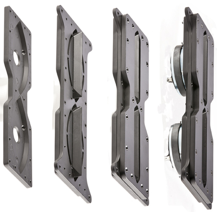
The second metamaterial I modeled for printing is actually the basis of the Kef design, just not suitable for a tweeter in its block form.
The second metamaterial I modeled for printing is actually the basis of the Kef design, just not suitable for a tweeter in its block form.
I've been unable to find the paper that you based your designs on.
In regards to donor tweeters, here's what I tried:
B&C DE250 - best option. Phase plug is removeable, it's not even glued, it's press fit. Back chambers is removeable.
SB Acoustics SB26ADC - I nearly destroyed this trying to remove the back plate. I think it's epoxied on. To get it off, you'd probably have to saw it off.
Peerless DA25BG08-06 1" Aluminum Dome Tweeter 6 Ohm - This is my 2nd favorite. Back plate is easily removed and the glue seems to be something like rubber cement. Can easily be re-attached.
For testing purposes perhaps an open back planar driver would work? Fewer constraints imposed by the motor structure. That may not be the final application for lots of folks but it might be a nice starting point for experimentation.
Few
Few
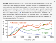
Some have noted that a lot of this might be a marketing gimmick. Here's some data comparing fiberglass versus a different type of metamaterial.
Note that the metamaterial is about 100% more effective. Of course, that begs the question, what if you just used 2X as much fiberglass?
Having said that, it *does* seem that the attenuation of fiberglass maxes out at about 10dB in this test.
Of course, all of this is complicated by a million factors:
- There's a hundred different ways to make a metamaterial
- The effectiveness of metamaterials is dependent on angle. IE, you could have one with high attenuation at zero degrees and less attenuation off axis. This could be a defect or a feature.
- The behavior of fiberglass and metamaterial will depend on whether it's inside an enclosure, or on a wall. IE, metamaterials might be better for acoustic treatment, where it's not practical / attractive to have a wall covered in ugly acoustic treatments.
Attachments
In post 47, I said I couldn't find the doc.
I found it : (PDF) Three-dimensional labyrinthine acoustic metamaterials
I didn't notice the PDF link, the first time around.
I found it : (PDF) Three-dimensional labyrinthine acoustic metamaterials
I didn't notice the PDF link, the first time around.
Here's a metamaterial absorber from Chen Shao at Nanjing University. The absorber achieves nearly 100% absorption at a single frequency, and over 40% absorption in a one octave band from 140Hz to 280hz:
(PDF) Low-frequency perfect sound absorption achieved by a modulus-near-zero metamaterial

I read the doc forwards and backwards, and I don't see *anywhere* where they lay out how to design their absorber. But if you get out a tape measure and just measure the pictures, it's *clearly* a quarter-wavelength transmission line that's folded.

If you want to make one yourself, here's what it looks like.
Here's some speculation on my part, on how this thing works:
That's the best explanation I can make for it. Because it seems like you'd want one end to be closed, if you're going to make the channels one quarter wavelength, instead of one half wavelength. Channels that are one half wavelength long would delay the signal by (you guessed it) one half wavelength, and would put it out out of phase with the energy reflected off of the wall. So there must be some type of a reflection in the labrything, to give us that 180 degree phase reversal. IE, we'll have a wave that's out of phase IF the sound that enters is reflected off the end of the labryinth.
This kinda makes me wonder why they bother to use an open end on one side?
But I have that answer coming shortly...
(PDF) Low-frequency perfect sound absorption achieved by a modulus-near-zero metamaterial
I read the doc forwards and backwards, and I don't see *anywhere* where they lay out how to design their absorber. But if you get out a tape measure and just measure the pictures, it's *clearly* a quarter-wavelength transmission line that's folded.
If you want to make one yourself, here's what it looks like.
Here's some speculation on my part, on how this thing works:
- Step 1: sound enters the transmission line from the outside of the tube
- Step 2: the sound is delayed by one quarter wavelength. A fraction of the sound exits through the opposite end.
- Step 3: a fraction of the sound is reflected, and radiated back out through the opening. This is due to the impedance mismatch at the exit.
That's the best explanation I can make for it. Because it seems like you'd want one end to be closed, if you're going to make the channels one quarter wavelength, instead of one half wavelength. Channels that are one half wavelength long would delay the signal by (you guessed it) one half wavelength, and would put it out out of phase with the energy reflected off of the wall. So there must be some type of a reflection in the labrything, to give us that 180 degree phase reversal. IE, we'll have a wave that's out of phase IF the sound that enters is reflected off the end of the labryinth.
This kinda makes me wonder why they bother to use an open end on one side?
But I have that answer coming shortly...


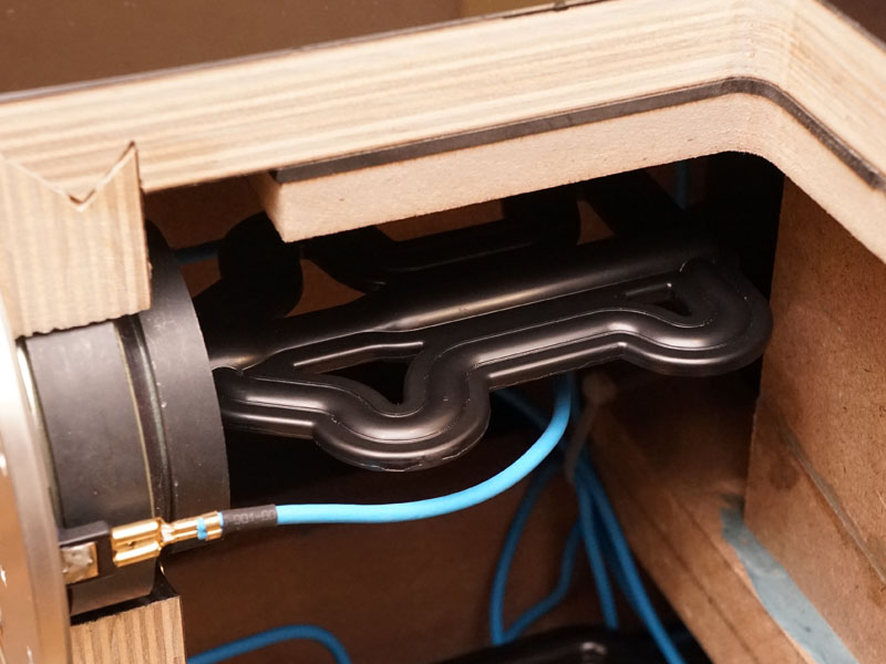
Here's the latest sound absorber, from the same author as post 51.
As you can see, it's basically a transmission line subwoofer, minus the driver.
This is definitely something you could simulate in hornresp; just model a tline in hornresp, and remove the contribution of the driver itself.
A few thoughts:
- If you look at the performance of the old design, it's superior. My hunch on why the old one works better than the new one, is that I think that a fraction of the incoming soundwave is reflected by the exit of the transmission line, while a fraction of it exits. I think this explains why the old one is much broader in spectrum. Basically it behaves like a half-wavelength resonator for reflected waves, and a quarter wavelength resonate for waves which pass through without reflection. Due to this, it behaves as if it's two different lengths. On top of that, the old design has massive numbers of bends, and I imagine that those 180 degree bends are introducing turbulence. This would have the effect of delaying some of the sound, but not all. This would probably also indicate that the effectiveness of the absorber is SPL dependent.
- Since the new absorber is basically a plain ol' transmission line, it would be really interesting to see if you could broaden the resonance by playing with the offset of the entrance. All of the metamaterial designs that I've seen so far, they all place the entrance to the labyrinth at the end of the line. But as we know from tapped horns and tlines, that's generally the worst place to put the mouth.
Full article here:
Subwavelength broadband sound absorber based on a composite metasurface | Scientific Reports

Nearly all of the metamaterials use a circular or square hole as an entrance to their labyrinth.
I think a Danley Paraline might work better.
As we know, the Paraline takes a circular source and turns it into a ribbon shaped source. For a metamaterial absorber, you could do this in reverse:
Have a long ribbon shaped ENTRANCE which exits to a round or a square hole.
This has a series of benefits:
- All of the material on metamaterials seems to indicate that there's turbulence at the bends. Turbulence attenuates the SPL level. In a Paraline, this is a PROBLEM. For instance, my early Paraline experiments were crude, and I was seeing an SPL loss of as much as 10dB due to the reflectors in my early Paralines. As I got better at making Paralines, I was able to fix that to a great extent, by being VERY exacting about the geometry and by using the gentlest bends possible. But in a metamaterial absorber, a lost of ten decibels is GREAT NEWS! That's a feature, not a defect. It basically means we're destroying some of the SPL right inside of the lens.
- By using a long, tall slot, we can reduce the directivity of the metamaterial. If you look at the papers, a lot of these metamaterials only work best if the sound is DIRECTLY in front of the metamaterial. This is because they destroy sound via pathlength differences, and if the sound source is off-axis, the pathlengths aren't correct. Paraline fixes this, because it's coverage is constant from top to bottom. Heck, if you were really creative, you could probably make a Paraline absorber that focused at a point in the room! For instance, I live near a freeway. I could build a Paraline absorber that's focused at the window of my bedroom, to absorb incoming sound from the window :O
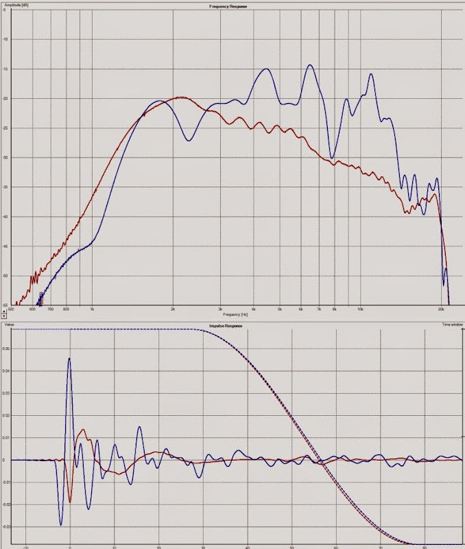
Here's a pic describing what I meant from post 53. Basically a poorly terminated Paraline will have deep nulls, caused by reflections. The reflections are due to an impedance mismatch. Normally, that's a BAD thing, but if you're TRYING to make something that nullifies sound, that could be good. Particularly if you can build 15-30 of these, all tuned to different resonances.
Again, this performance is not typical of a well built Paraline; this Paraline basically had no termination, which leads to harmonic dips in the response, caused by higher order modes.
The jagged line is my poorly built paraline, the smooth line is a qsc waveguide, both devices were driven by the same compression driver with the same voltage.
I cracked open my Peerless DA25.

Here's a DATS measurement with the sealed chamber

Here's a DATS measurement with the chamber open. Basically removed the backplate of the tweeter, which was glued on.

Here's the predicted response, from Hornresp. I used two different models. The first model, the smooth one, is a simple sealed box. The second model - with the giant dip in the response - is a "closed transmission line." This is a little used option in Hornresp, where you can simulate closed transmission lines like the B&W Nautilus.
Obviously, the "closed transmission line" sim is exaggerating the impact of the reflection off of the back chamber.
I think this is how this works:
Of course, that last part, I believe it depends on the rigidity of the driver, what stuffing there is in the chamber, the motor force of the driver, etc. As I understand it, this is similar to how a powered loudspeaker in a room can excite an unpowered speaker. But the effect is far less significant if the other speaker has something to keep it's cone from moving, such as being plugged into an amplifier.
IE, David McBean can correct me on this, but I have a hunch that the "closed transmission line" option in Hornresp is basically treating the loudspeaker as if it's a passive radiator.
This is hideously complex, obviously. But hooray for Hornresp, because I'm not aware of any other way to model a closed back transmission line, except for Akabak. Which has been abandonware for 10+ years.
Here's a DATS measurement with the sealed chamber
Here's a DATS measurement with the chamber open. Basically removed the backplate of the tweeter, which was glued on.
Here's the predicted response, from Hornresp. I used two different models. The first model, the smooth one, is a simple sealed box. The second model - with the giant dip in the response - is a "closed transmission line." This is a little used option in Hornresp, where you can simulate closed transmission lines like the B&W Nautilus.
Obviously, the "closed transmission line" sim is exaggerating the impact of the reflection off of the back chamber.
I think this is how this works:
- In a conventional transmission line, with an open back, the rear wave of the driver exits out of the mouth of the transmission line and it augments the *front* wave of the driver.
- In a closed transmission line, with a closed back, the rear wave of the driver is reflected back to the throat of the transmission line. Because it's out of phase with the back of the driver, you get a dip in the response.
Of course, that last part, I believe it depends on the rigidity of the driver, what stuffing there is in the chamber, the motor force of the driver, etc. As I understand it, this is similar to how a powered loudspeaker in a room can excite an unpowered speaker. But the effect is far less significant if the other speaker has something to keep it's cone from moving, such as being plugged into an amplifier.
IE, David McBean can correct me on this, but I have a hunch that the "closed transmission line" option in Hornresp is basically treating the loudspeaker as if it's a passive radiator.
This is hideously complex, obviously. But hooray for Hornresp, because I'm not aware of any other way to model a closed back transmission line, except for Akabak. Which has been abandonware for 10+ years.
Sent a DM, but as your active in the thread:
"The Peerless DA25BG08-06 looks like a great candidate for testing, thanks for the heads up. Was looking at the tweeters I have used and considered using in the future and they all look like a massive pain to open up.
Do you have any pictures of the tweeter opened up? If you still have one would you be willing to open it and take measurements (the diameter of the throat at the exit would be the minimum)? Basically what is needed is a clear shot to the diaphragm out the back of the magnet for the meta material to work."
I have started to model a meta material with a 19mm diameter throat for broad band damping of a tweeter like the DA25BG8-06 (assuming the diameter for now).
Here is a script (MATLAB or Octave) I wrote to find the lengths of the FP tubes on a log scale. I have it set to find me 32 tubes tuned to the 1/4 wave between 400 and 6k Hz at the nearest 0.25 mm.
% This script is to find channel lengths for a Fabry-Perot type
% metamaterial.
%
% Input:
% minFreq - absorber's minimum center frequency
% maxFreq - absorber's maximum center frequency
% N - number of Fabry-Perot channels
% round - rounding interval
%
% Output:
% series - the rounded lengths of the channels
% count - then number of rounding intervals that make a channel's length
minFreq = 400;
maxFreq = 6000;
M = 343; % m/s
N = 32;
round = 0.25;
m2mm = 1000; % meters to milimeters
minL = M / minFreq / 4;
maxL = M / maxFreq / 4;
series = logspace(log10(minFreq),log10(maxFreq),32)';
series = series ./ max(series);
series = minL * m2mm * series;
series = floor(series) + ceil( (series-floor(series))/round) * round;
series = floor(series) + floor( (series-floor(series))/round) * round;
series
count = series ./ round
David McBean can correct me on this, but I have a hunch that the "closed transmission line" option in Hornresp is basically treating the loudspeaker as if it's a passive radiator.
Hi PB,
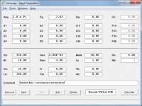
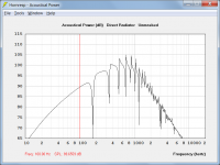
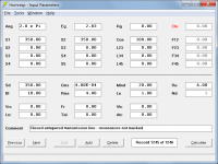
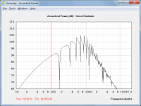
When the 'resonances not masked' option is selected both sealed box and closed transmission line systems are analysed the same way by Hornresp. This can be confirmed by comparing a sealed box with an untapered closed transmission line system of the same dimensions. As shown in the attachments the 'resonances not masked' results are identical. Tapering a closed transmission line simply alters the calculated acoustical impedance loading the rear side of the driver diaphragm. The simulation model itself does not change.
Kind regards,
David
Attachments

While looking at the experimental data, I noticed that there's room for improvement with these things.
As I understand it, these are basically a series of resonant channels.
When we build transmission lines in Hornresp, we need to do two things as we go lower and lower in frequency:
- We have to make the transmission line longer
- We have to make the cross section larger
In the metamaterial, they've only satisfied the first requirement.
When we make transmission lines that are too small, we see that the resonant peaks are narrower, and the metamaterial exhibits the same issue: note how the low frequency resonances are much narrower in bandwidth.
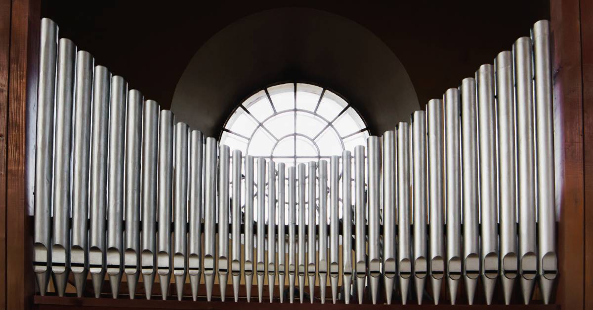
Church organs follow the same principle.
TLDR: one could improve the metamaterial, by using channels which start out small in diameter, and increasing grow larger in diameter.
Sent a DM, but as your active in the thread:
"The Peerless DA25BG08-06 looks like a great candidate for testing, thanks for the heads up. Was looking at the tweeters I have used and considered using in the future and they all look like a massive pain to open up.
Do you have any pictures of the tweeter opened up? If you still have one would you be willing to open it and take measurements (the diameter of the throat at the exit would be the minimum)? Basically what is needed is a clear shot to the diaphragm out the back of the magnet for the meta material to work."
I have started to model a meta material with a 19mm diameter throat for broad band damping of a tweeter like the DA25BG8-06 (assuming the diameter for now).
Here is a script (MATLAB or Octave) I wrote to find the lengths of the FP tubes on a log scale. I have it set to find me 32 tubes tuned to the 1/4 wave between 400 and 6k Hz at the nearest 0.25 mm.
This is awesome, I was able to get this working in Windows in about ten minutes.
In the metamaterials that you designed, did you do the folding manually? Or did you find some way to fold it?
So I wasted the better part of my weekend, designing a series of 3D labyrinths. Every one of them became problematic, in particular trying to figure out how to fold 20-30 channels.

So I'm starting to lean this direction.
The concept is the same as this rectangular one, pictured above. But the channels are hexagonal, so the entire thing can be folded into a tube, so the tube can be epoxied to the back of a conventional tweeter.
Obviously, my hexagonal design isn't finished, it's just a cutaway of what it would look like, but if I can figure out how to fold 19 channels into it, I think it should be 3D printable, and about the right size.
To give you an idea of the scale:
Keep in mind, this is still a sealed enclosure, so all the normal rules apply. IE, if the enclosure becomes too big that can be problematic.
I modeled some closed transimission lines for the Peerless DA25, and they looked REALLY nice. Basically the closed transmission line gives you a rolloff that's realllllly gradual. Assuming I load this thing in a waveguide, that could be a really nice combo. Basically I would size the waveguide so that the horn gain of the waveguide complements the inherent rolloff of the tweeter, yielding a one inch dome that can probably be crossed over at about 500-700Hz.
So I'm starting to lean this direction.
The concept is the same as this rectangular one, pictured above. But the channels are hexagonal, so the entire thing can be folded into a tube, so the tube can be epoxied to the back of a conventional tweeter.
Obviously, my hexagonal design isn't finished, it's just a cutaway of what it would look like, but if I can figure out how to fold 19 channels into it, I think it should be 3D printable, and about the right size.
To give you an idea of the scale:
- Kef is using 30 channels in theirs, and they appear to measure 2mm x 2mm
- The one I've pictured, has 19 channels with a diameter of approximately 3.9mm. The overall diameter of the tube is 25.4mm
- The depth of the device would be about 125mm
- I can reduce the overall width to 12.7mm with 1.95mm channels. Or anything in between really.
Keep in mind, this is still a sealed enclosure, so all the normal rules apply. IE, if the enclosure becomes too big that can be problematic.
I modeled some closed transimission lines for the Peerless DA25, and they looked REALLY nice. Basically the closed transmission line gives you a rolloff that's realllllly gradual. Assuming I load this thing in a waveguide, that could be a really nice combo. Basically I would size the waveguide so that the horn gain of the waveguide complements the inherent rolloff of the tweeter, yielding a one inch dome that can probably be crossed over at about 500-700Hz.
- Home
- Loudspeakers
- Multi-Way
- 3D Printed Metamaterials