Hi Everyone,
I have a problem with these speakers I just finished.
It's a 2-way ViMo speaker-kit I bought from lautsprechershop.de.
When I hook them to my amplifier the tweeter sounds very quiet and distant and the woofer doesn't do anything at all. It's the same for both speakers.
I've tried a different amp, wires and source but alas. The sound is always the same. I'm fairly sure the crossover is constructed correctly (I double checked this).
Does anyone know what might be the cause of this problem?
Kind regards!
Michiel
Welcome to the forum, Michiel!
I will add a helpful link to your kit: ViMo
To gauge your degree of experience, may I ask if this is your first loudspeaker build?
To eliminate your crossover construction as being the problem, please supply photographs of the finished crossovers and a crossover schematic for comparison purposes.
I will add a helpful link to your kit: ViMo
To gauge your degree of experience, may I ask if this is your first loudspeaker build?
To eliminate your crossover construction as being the problem, please supply photographs of the finished crossovers and a crossover schematic for comparison purposes.
Thanks Galu!
Here are the pictures from the crossover and the schematic.
This is my 4th speaker project so it isn't something new to me.
Although I must admit that I don't have much experience with soldering (something to work on I guess). I take more bride in the woodworking part of the hobby...
Here are the pictures from the crossover and the schematic.
This is my 4th speaker project so it isn't something new to me.
Although I must admit that I don't have much experience with soldering (something to work on I guess). I take more bride in the woodworking part of the hobby...
Attachments
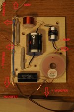
Disconnect the crossover from your amp and meaure the resistance of the inductor in the lowpass filter. Should be less than 1 ohm. May be a poor solder connection, especially if you didn't do a good job of removing the insulation from the inductor wire.
Yes, did you scrape off the enamel coating on the ends of the inductor wires
before soldering them? Also the soldering in general needs to be better.
Soldering tips and tricks
– Rising Sun FPV
before soldering them? Also the soldering in general needs to be better.
Soldering tips and tricks
– Rising Sun FPV
Assuming you've tested your amp with good speakers:
Unsolder tweeter 3.3uF cap from crossover + input to separate the woofer & tweeter circuits.
Clip amp output wires to woofer then work back to crossover input until sound is lost.
Do the same with tweeter but through a protective capacitor (say borrow the 3.3uF from the speaker not under test if you don't have a spare).
If you are suffering a mid-range loss, one driver may be out of phase (swap +/- of one driver only).
When fixed, label all clearly for future ref.
Yes, I've got to agree that those solder joints look rather iffy!Although I must admit that I don't have much experience with soldering (something to work on I guess).
The joint should first be mechanically sound (twist wires together). Hold the tip of the soldering iron against the joint. Touch the solder to the junction between the iron tip and the joint and let the molten solder flow over the joint. Aim for a smooth finish, not ragged as many of your joints appear.
Oh! And has been said, make sure you first scrape of any enamel on the wires!
Hmm - here is what I would do:
a) Disconnect the cross-over and connect the woofer directly to the amplifier. You should hear the woofer play. This will verify that the woofer units work.
b) Assuming we are fine this far, reconnect the woofer part of the cross-over only. Big inductor and black 22uF cap across it. Now try to play with the woofer and woofer crossover only. Should sound roughly the same as before - but with a bit less upper midrange.
c) If we got this far, then the woofers are fine. Now repeat step b) with the dome tweeter - but DO NOT test without the tweeter cross-over. Keep the polarity on the woofer and the dome tweeter the way it is in the schematic.
Breaking the testing into these steps ensure against swapping wires by mistake.
Good luck.
D.
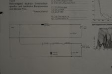
The cut-off frequencies for woofer and tweeter seem to be at very different, something is wrong with the design or component values I think, dropping a big hole in the response.
I make the woofer cutoff 880Hz and tweeter about 3.5kHz.
Random thought: perhaps this is a 3-way design that's been erroneously adapted for 2-way?
What is the nominal cross-over frequency? Put that into a cross-over design app and see what component values you get.
I make the woofer cutoff 880Hz and tweeter about 3.5kHz.
Random thought: perhaps this is a 3-way design that's been erroneously adapted for 2-way?
What is the nominal cross-over frequency? Put that into a cross-over design app and see what component values you get.
Last edited:
Follow the link in post 2.
'The crossover consists of a 3rd order high-pass filter (18 dB per octave slope) for the tweeter. The woofer are connected to a 2nd order low pass filter (12 dB per octave slope).'
'crossover frequency(s): 1800 Hz'
Values on schematic match components stated on webpage.
'The crossover consists of a 3rd order high-pass filter (18 dB per octave slope) for the tweeter. The woofer are connected to a 2nd order low pass filter (12 dB per octave slope).'
'crossover frequency(s): 1800 Hz'
Values on schematic match components stated on webpage.
The component values seem completely wrong for those parameters, checkout this calculator:
HiFi Loudspeaker Design
I make suitable LR2 woofer values 680µH / 11µF
and tweeter 8.5µF / 0.5mH / 11µF or so (assuming a load of 10 ohms from the resistor pad)
HiFi Loudspeaker Design
I make suitable LR2 woofer values 680µH / 11µF
and tweeter 8.5µF / 0.5mH / 11µF or so (assuming a load of 10 ohms from the resistor pad)
Ok, I fixed the problem.
@vilfort: I followed your instructions and discovered that both the woofer part and tweeter part work fine separately. So I came up with the idea of switching the polarity of the woofer and that did the job! Although I have no idea clue why this works...
@rayma: Thanks for soldering tips. Increasing the temperature of my soldering iron helps a lot.
@Mark Tillotson: What software would you recommend?
Thanks for your reactions everyone!
Sometimes 3rd order Xovers do have polarity reversal, for eg ESS did on some designs.
You can check the effect with an spl meter and a tone generator set to the Xover frequency by moving the meter in an arc across the drivers.
At Xover the drivers should add if the phase is correct, if not a deep null in O/P will result as you sweep.
You can check the effect with an spl meter and a tone generator set to the Xover frequency by moving the meter in an arc across the drivers.
At Xover the drivers should add if the phase is correct, if not a deep null in O/P will result as you sweep.
A crossover calculator won't give you reasonable values because the impedance of the drivers isn't a simple resistance, and the designer is probably also compensating for the responses of the drivers (e.g. break up in the woofer) and baffle step compensation.The component values seem completely wrong for those parameters, checkout this calculator:
HiFi Loudspeaker Design
I make suitable LR2 woofer values 680µH / 11µF
and tweeter 8.5µF / 0.5mH / 11µF or so (assuming a load of 10 ohms from the resistor pad)
Ok, I fixed the problem.
@vilfort: I followed your instructions and discovered that both the woofer part and tweeter part work fine separately. So I came up with the idea of switching the polarity of the woofer and that did the job! Although I have no idea clue why this works...
@rayma: Thanks for soldering tips. Increasing the temperature of my soldering iron helps a lot.
@Mark Tillotson: What software would you recommend?
Thanks for your reactions everyone!
Credit where it's due - I got there 2 posts earlier (post #6). 😉
Glad you fixed them.
Many years ago I bought then returned a pair of speakers from Richer Sounds.
No matter how loud I turned the amp the sound was quiet and muddied.
Looking back I am convinced it must have left the factory with drivers wired opposite phase.
I didn't know then but it would have been easy to test as it had separate woofer & tweeter binding posts for bi-wiring. I was using single speaker cabling & linked the posts as intended, red to red, black to black.
Improper polarity won´t go from ZERO output to perfect sound, at worst it will sound weakish and weird (big hole in midrange) so my take is there was some terrible soldering involved and now you corrected it.Ok, I fixed the problem.
switching the polarity of the woofer and that did the job! Although I have no idea clue why this works...
- Home
- Design & Build
- Construction Tips
- Problem with diy speakers