I have another thread relating to PCB procurement for a Quad 405-2 but as this is common to many amplifiers I thought to create a new thread.
I require 2 inductors 3uh for the bridge circuit and a 22uh in the output circuit. From reading it appears the 22uh tolerance is not so important but the 3uh should be tight.
I do not know what the original current rating was for each item, a search on ANCO 440 leads here and nowhere else of use. I have thought about winding these myself on ferrite cores but the online calculators suggest something fairly huge if I specify 18AWG wire on the 22uf. If I wind them my work will be very accurate but I have no means to measure the resulting inductance so how accurate are the calculations transposed to wire and ferrite? Would it be possible to follow the recipe from the calculator and arrive at a tight tolerance or does someone who has built Quad clones have some product links?
There is another older thread related to this question, I do not consider it was resolved, there was also some contention.
Last edited:
When building Elvee's "EZ Dump" amp (EZ-Dump: dump your current without really trying), I used this inductor:
RLB0914-3R3ML Bourns | Mouser
and it worked perfectly.
Perhaps you can find 3uH of the same type.
Tolerance on these products is 20%, so even 3.3uH will fit 🙂
RLB0914-3R3ML Bourns | Mouser
and it worked perfectly.
Perhaps you can find 3uH of the same type.
Tolerance on these products is 20%, so even 3.3uH will fit 🙂
Last edited:
Check it with an online calculator but guess 3uH is but a few turns wire.
Easier DIYing than ordering.
Easier DIYing than ordering.
For clarity, try: Pronine Electronics Design - Single-Layer Air Coil Calculator
and Pronine Electronics Design - Multilayer Air Core Inductor Calculator
Apart from DIY basics like measuring wire size, coil diameter and length, you need to wind the wire on a suitable size former like a pen, dowel or even a bolt. It's intuitive, not really difficult as as long as you have some enamelled copper wire of approximately correct and known diameter to begin with. And as it's enamelled wire, you may need to clean the ends on old wire to tin them and you'll need a substantial soldering iron and tip to do that and also to solder them in place.
I'm good for the tools, I have pin gauges in 0.1mm steps to 12mm and a Weller soldering gun should have enough grunt.
I tried two calculators, one for ferrite cores and one for air core.
Pronine Electronics Design - Multilayer Air Core Inductor Calculator
Coil32 - Ferrite Rod Coil Calculator
I see a candidate for the lower value inductor in the replies but its 3.3uh at 20% so if I luck out in what gets picked from the bin it might be 3.96mh. The bridge circuit on paper calls for 2.82mh which of course never existed as an off the shelf item.
It looks like I will be brewing my own 22uh and the 3uh perhaps off the shelf solution. I am still stuck as to the current rating for the 22uh in the output circuit, I am a rank amateur and the calculations required would make my eyes bleed just to look at the equations. I am going to take a stab at 8A, if the thing makes for a hand warmer when I apply some power I'll know I have underdone the wire gauge😀.
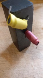
I've got a home built 405 which has been in use on and off for almost 40 years. The coils are hand wound air core. These pictures might help to visualise the required coils.

As I mentioned in the original post there is contention. In this thread Help: inductances in original Quad405. member Ouroboros said he/she would try a magnet on a spare board but there the thread ends.You must use air-core, not ferrite core.
Keith Snook takes a pop at people winding what amount to radio receivers in another thread here that touches on these components.
Can you say with certainty that the two values used by Quad are air cored or at least the more sensitive 3uH piece is air cored?
Looks like I am one step closer here, do you recall what gauge wire the two 6.9uH (405-1?) are on your board?I've got a home built 405 which has been in use on and off for almost 40 years. The coils are hand wound air core. These pictures might help to visualise the required coils.View attachment 878159
It is a 405-1. I don't know the gauge but hopefully someone might tell from the pictures, or I can try to measure the wire.
I have looked at photos of various mods both commercial and homebrew and none show the 22uH without a sleeve of some sort but the 3uH on the Net Audio boards at least is definitely air cored.
I have been playing with the calculators and Coil32 has a sane looking recipe with 20AWG wire and a 10mm former, its still quite meaty in comparison to the piece fitted to production Quads though at nearly 12mm OD for its 23mm between pins PCB position. Using 22AWG and an 8mm former gives just shy of 23mm length with OD of 9.4 which looks to be about the size of the ANCO piece used by Quad.
On the strength of the little I know the bridge circuitry would not worry 22AWG wire. So one down and one to go.
The 22uH with air core gives recipes for huge coils at 18AWG. The multi layer calculator gives a monster of 5 layers on a 4mm former, that is an OD of 15mm if its length is to fit the board! Perhaps Quad used a ferrite cored piece for the larger value. Someone with a magnet and a board could help. I would not fancy less than 18AWG due to its position in the output circuit.
For both values of inductor?Definitely nothing like 18AWG though. Probably somewhere 24-28
When you say it comes out huge. Did you try making the diameter bigger?
Also 18AWG is just over a mm diameter wire. That's pretty heavy. I just don't see a need for that for peaks of 8A. This amp runs cool most of the time (it's class B, remember? Well, 405-2 is more like AB).
Also 18AWG is just over a mm diameter wire. That's pretty heavy. I just don't see a need for that for peaks of 8A. This amp runs cool most of the time (it's class B, remember? Well, 405-2 is more like AB).
22uH: My estimate(!)
inner diameter of former (bobbin): 50mm
length of coil:5mm
15 turns of 1mm copper wire wound in 3 layers of 4 turns and 1 layer of 3 turns.
NOt built nor tested, no guarantees, but you could test one using a tight tolerance cap (e.g. 1nF silver mica 1%) and a feedback winding (1 turn?) to make an oscillator and measure the freuqnecy?
For the 22uH I tried several gauges that would give a coil length to fit the PCB drillings, its not possible as a single layer. With multi layer and 22AWG it will foul neighbours on width unless the legs are longer by 4mm.When you say it comes out huge. Did you try making the diameter bigger?
Also 18AWG is just over a mm diameter wire. That's pretty heavy. I just don't see a need for that for peaks of 8A. This amp runs cool most of the time (it's class B, remember? Well, 405-2 is more like AB).
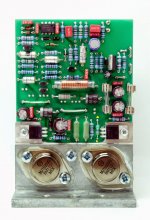
The job changed today, clone 405-2 boards arrived from China and an et voilá moment occured regarding the 22uH inductor. The earlier clone boards I built used the same no name pink and blue devices sold seperate from the full kits and ready assembled boards, so 3uH and allegedly 6.9uH. On the early boards the two coils in the output circuit have some space away from TR7 and TR8 with 1.5mm drillings but the 405-2 clone has a 1mm drilling and is really close to TR8.
I have browsed all the materials I could find on these amplifiers and not once did I recognise or look for the coil L4 on the 405-2 boards.
So while checking through the PCB layout differences between Jims audio clone board and an image of the real thing I see that L4 is actually quite puny compared to the 2x devices on the early boards. Hole centres on the 405-2 for L4 are 13mm so probably a device no longer than 7.5mm which suggests a lot less than 1A, a very lot less.
There are plenty of off the shelf candidates at 5% for the 22uH, I don't think I have any magnet wire of small enough gauge. If I use the calculator and set the coil length the same as a Bournes of similar size to what is on the OEM board I get close enough to package size with 34AWG, rated 300mA for chassis wiring.
So I hand wind the 3uH coil and try to identify the part used by Quad for the 22uH.
Attachments
I can't, I gave my olde worlde Tektronix scope away years ago, the only test gear I have a hand to is a Fluke 177 and a decent bench supply. Moving home to another country involves some ruthless decisions, if I could wind the clock back I would have taken the lot.22uH: My estimate(!)
inner diameter of former (bobbin): 50mm
length of coil:5mm
15 turns of 1mm copper wire wound in 3 layers of 4 turns and 1 layer of 3 turns.
NOt built nor tested, no guarantees, but you could test one using a tight tolerance cap (e.g. 1nF silver mica 1%) and a feedback winding (1 turn?) to make an oscillator and measure the freuqnecy?
I think I will look for a used scope and a function generator, more fun than the TV on the long winter nights.
OK If I get a chance I'll build one and measure it. 1nF should have given 1.06MHz.
Pity you couldn't keep your scope! It's essential, I've found!
Could you try 100nF (larger caps tend to come at looser tolerance) for 100kHz - your Fluke might measure that. or 220nF?
I'll check also the simulation of an oscillator.
Pity you couldn't keep your scope! It's essential, I've found!
Could you try 100nF (larger caps tend to come at looser tolerance) for 100kHz - your Fluke might measure that. or 220nF?
I'll check also the simulation of an oscillator.
Last edited:
Very interesting. Probably this type of inductor (for the 22uH) or something off the shelf which will fit is readily available, at least. All the best with your build [emoji2]
You can trust the industrious factories of China to muddy the waters further. I bought a bag of the no name coils in the attached pic to complete my first build. as you can see there is more ferrous material than air. 😀You must use air-core, not ferrite core.
Attachments
- Home
- Amplifiers
- Solid State
- Seeking inductors 3uh and 22uh, yes for a Quad 405