For sure, the 22uH would be a bind to wind even using my lathe to spin the former but the 3uH one I will take some pleasure in as the first coil I have wound since about 1973. The footprint on the board is huge for the 3uH, 30mm centres with a lot of space for the width.Very interesting. Probably this type of inductor (for the 22uH) or something off the shelf which will fit is readily available, at least. All the best with your build [emoji2]
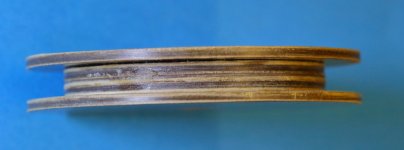
Well, I just had to try one. Here are some pix of the bobbin and oscillator using the coil with a single turn taped on the outside for a temporary feedback winding.
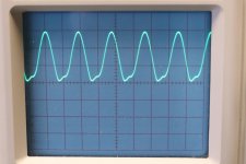
You can see that there are 4 cycles in 3.75us (0.5us/div) making the frequency 1.067MHz.
Theoretical osc. frequency is 1.073MHz. Not taken transistor capacitance into account.
The bobbin was constructed from three disks of 50mm diameter, two 2mm thick and one 1.5mm thick, SRBP, although after constructing, I think 1mm would have been better than the 1.5mm. Two larger disks about 63mm were used for the outsides. These were actually the "holes" or the insides of holes cut using hole saws of 54 and 67mm diameter respectively. The inside diameter measured 49.7mm after gluing and sanding. Conveniently the 6mm pilot drill provides a central hole which can be used to align them.
I aimed at winding 4 turns per layer, and you need to allow for 1 turn to get the "last turn" in , plus thickness of the insulation on the wire. As it happened, I got about 4.75 turns before the layer folded back on itself, but the total number of layers was 4 for the 15 turns.
The circuit simulation measures 1MHz for the same component values. That may mean the inductance is 6% low (but the scope accuracy is only 3% on timebase). Anyway, back to the computer. Recalculated the inductance with 49.7mm diameter - result, 21.5uH! A half-turn would fix that.
Conclusion: if you use 50mm diameter exactly, inductance should be 22uH. Not a guarantee, though!
(I don't use a lathe to turn coils. Too often wires have broken. For this one I just used a hand drill with the coil held in a 6mm bolt).
Not sure if that helps. But it was an interesting diversion for a morning.
Which reminds me, I must finish the inductance meter project I started.
Attachments
Last edited:
Correction/update:
I changed the entries slightly on the 49.7mm diameter calculation. The difference between the 49.7 and 50mm is not 0.5uH but only about 0.1uH when all else is equal. The lower inductance was because I also spaced the turns out slightly as well. The original calculation still stands that the winding needs to be 4 turns per layer, close wound with 3 turns in the final layer. Keeping the bobbin core to 5mm thick should help.
I changed the entries slightly on the 49.7mm diameter calculation. The difference between the 49.7 and 50mm is not 0.5uH but only about 0.1uH when all else is equal. The lower inductance was because I also spaced the turns out slightly as well. The original calculation still stands that the winding needs to be 4 turns per layer, close wound with 3 turns in the final layer. Keeping the bobbin core to 5mm thick should help.
Last edited:
... coorection (2)
I forgot the square root!
If the simulation says 1MHz for a 22uH coil and the circuit measures 1.06, the coil error is of course not 6% but 13%. Comparing simulation to measurements.
But the simulation shows that the current is very peaky. That causes a large signal parametric change through the cycle, and relying on clipping to control the gain may well cause difference to small-signal behaviour.
So I think I prefer to trust the measurements at the moment.
I'll see whether I can measure the inductance more accurately when I have another spare moment.
Having thought about it after the last post, I tried a modification to both the oscillator circuit and simulation. No observable change in frequency in the measurement, still 1.067MHz. The waveform however improved.
Simulation jumped to 1.048MHz, which is looking a lot closer.
Simulation jumped to 1.048MHz, which is looking a lot closer.
Cracking stuff! I feel some scope envy, I am going to start crusing ebay and leboncoin for a scope and a function generator. Today I found a decade box that escaped being launched or given away when I moved. Made it at work in 1976😀. How much accuracy with a scope can you measure an inductor?Well, I just had to try one. Here are some pix of the bobbin and oscillator using the coil with a single turn taped on the outside for a temporary feedback winding.
You can see that there are 4 cycles in 3.75us (0.5us/div) making the frequency 1.067MHz.
Theoretical osc. frequency is 1.073MHz. Not taken transistor capacitance into account.
The bobbin was constructed from three disks of 50mm diameter, two 2mm thick and one 1.5mm thick, SRBP, although after constructing, I think 1mm would have been better than the 1.5mm. Two larger disks about 63mm were used for the outsides. These were actually the "holes" or the insides of holes cut using hole saws of 54 and 67mm diameter respectively. The inside diameter measured 49.7mm after gluing and sanding. Conveniently the 6mm pilot drill provides a central hole which can be used to align them.
I aimed at winding 4 turns per layer, and you need to allow for 1 turn to get the "last turn" in , plus thickness of the insulation on the wire. As it happened, I got about 4.75 turns before the layer folded back on itself, but the total number of layers was 4 for the 15 turns.
The circuit simulation measures 1MHz for the same component values. That may mean the inductance is 6% low (but the scope accuracy is only 3% on timebase). Anyway, back to the computer. Recalculated the inductance with 49.7mm diameter - result, 21.5uH! A half-turn would fix that.
Conclusion: if you use 50mm diameter exactly, inductance should be 22uH. Not a guarantee, though!
(I don't use a lathe to turn coils. Too often wires have broken. For this one I just used a hand drill with the coil held in a 6mm bolt).
Not sure if that helps. But it was an interesting diversion for a morning.
Which reminds me, I must finish the inductance meter project I started.
I can see a core, but is it really ferrous? The original inductors also have physical cores, but electrically it is air.as you can see there is more ferrous material than air. 😀
EJP
My scope is rated at +/-3% on timebase and 3% on volts. That suggests the RMS error is around 4.5% (max). Comparing with my DMM it seems to be about 1% on volts.
The circuit for the 405-2 shows the 22uH is in the driver stage not the output. The current will be much lower, and the inductor can be wound with thinner wire. That means more turns can be used on a smaller core.
Also, it would seem that it is not a critical stage compared with the 3uH which is part of the bridge. So my guess is that 5 or even 10% would be OK, but I've not looked at the Quad circuit in any depth to check.
Back to the drawing board?
Another way to measure the inductance: plug an oscillator into a power amp and feed the output into a dummy load and coil in series. I did this with a 15.67kHz signal source (almost any oscillator will do, does not have to be particularly low distortion, I have an old unit built many years ago adapted for filament lamp stabilisation as the original thermistor expired - just as they became obsolete or expensive). Using a 7.5 ohm dummy load I measured 3.1V across the resistor (in phase current) and 886mV across the coil using my DMM (about 0.1% accuracy). Giving the inductance as 21.7uH. That's about as accurate as I can measure. Which suggests if you were to use my design shown in the earlier post, don't take the wires out just before the 15th complete turn (the 15th turn was probably 10 degrees short of 360 due to the lead-out holes I drilled) but take the end past the start by about 10 degrees!
They stuck to my magnets a treat so.I can see a core, but is it really ferrous? The original inductors also have physical cores, but electrically it is air.
EJP
This I can do with my currently limited resources, thank you!Another way to measure the inductance: plug an oscillator into a power amp and feed the output into a dummy load and coil in series. I did this with a 15.67kHz signal source (almost any oscillator will do, does not have to be particularly low distortion, I have an old unit built many years ago adapted for filament lamp stabilisation as the original thermistor expired - just as they became obsolete or expensive). Using a 7.5 ohm dummy load I measured 3.1V across the resistor (in phase current) and 886mV across the coil using my DMM (about 0.1% accuracy). Giving the inductance as 21.7uH. That's about as accurate as I can measure. Which suggests if you were to use my design shown in the earlier post, don't take the wires out just before the 15th complete turn (the 15th turn was probably 10 degrees short of 360 due to the lead-out holes I drilled) but take the end past the start by about 10 degrees!
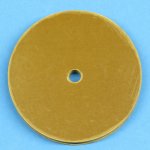
I took another look at the internet to see if there are any clues to the current rating of L2, the 3uH part. Dada website provided the answer with a picture of their "high end" boards. It is an Epcos 3uH 9A part EPCOS / TDK B82111B0000C016 and it has a ferrite core! It appears to have 15 turns.
I am still going to wind that piece myself, there seems to be overwhelming advice here and elsewhere to use air core for that part of a circuit.
Coil32 gives a recipe for 29 turns of 18AWG on a 10.5mm former making a total length of a fraction over 32mm, it will fit the board at that length. Kicking myself for not ordering 20AWG, could have had a smaller diameter and still been over speced for current.
Stock picture of the same family of product.
I am still going to wind that piece myself, there seems to be overwhelming advice here and elsewhere to use air core for that part of a circuit.
Coil32 gives a recipe for 29 turns of 18AWG on a 10.5mm former making a total length of a fraction over 32mm, it will fit the board at that length. Kicking myself for not ordering 20AWG, could have had a smaller diameter and still been over speced for current.
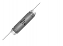
Stock picture of the same family of product.
Attachments
- Home
- Amplifiers
- Solid State
- Seeking inductors 3uh and 22uh, yes for a Quad 405