This may well develop into one of the many "phono input bias current"
discussions (at least a few minutes ago).
I built a large number of phono stages, some of them using Jan's regulators,
a few even using boards that he designed (these two amp examples not of
my design) and do not use input coupling caps. Be it base or emitter input I
never had any problems with input offset or current flow. This is a more than
25 years experience now.
Any electrolytic coupling cap is in big disadvantage here, because these do
not want to work without dc applied and this is also a big long term quality
problem in a particular historic amp series with only 0.5 V on the caps (emitter
voltage).
Read the DC voltage across R102 to indirectly measure the base current.
Those capacitors exist to keep base current out of the cart.
My preamps are direct-coupled to the cart but the bias current is low.
Those capacitors exist to keep base current out of the cart.
My preamps are direct-coupled to the cart but the bias current is low.
Consider the cap charging thump also ..
I guess RY 301 in the schematic of post #19 is meant to block that.
Is there a reason for keeping the original blue tantalum caps in this position/ application to replacing them with 'normal' electrolytes? (I know some people believe tantalums are the devil's work, apart from Naim 😉 )
I don't think so. Tantalum capacitors probably have a slightly lower loss angle and therefore slightly less thermal noise, but the noise of an aluminium electrolytic capacitor would also be far from dominant.
yeah right....the audiophile world hates tantalum in capacitors, but loves it in resistors...it's just the 2 million euro CT scan equipment that ignore audiophile world opinion and use them by millions in ultra low noise circuits because you can't hear the analogue to digital processing giving you a clear picture with your brain tumors...
Nichicon UES series inexpensive, great quality and sound.
You do want that cap it protects the cartridge if it does nothing else.
I would think you don’t want any DC on a cartridge in that it may offset the stylus but I may be wrong.
Nice looking pre.
You do want that cap it protects the cartridge if it does nothing else.
I would think you don’t want any DC on a cartridge in that it may offset the stylus but I may be wrong.
Nice looking pre.
[HA-55 is very close, both use parallel tantalums too
anyone measure a panasonic poscap for noise?
anyone measure a panasonic poscap for noise?
Attachments

Last edited:
You could use a bipolar elcap. I tried Flolyt EKMU, EKSU, ELNA RBD and Nichicon UES.
When you read Bateman carefully you can spot a trick that reduces distortion 8 fold over an optimally biased polar electrolytic by putting two bipolars in series. You could even make a stack of 4, parallel, series.
When you read Bateman carefully you can spot a trick that reduces distortion 8 fold over an optimally biased polar electrolytic by putting two bipolars in series. You could even make a stack of 4, parallel, series.
Anyway, I just build an AC coupled pre-pre with a 330uF 35V LXZ elcap biased to 0,6V bypassed with an 0,47uF SMD PPS and how hard I try I can not hear any loss of detail, sound staging or dynamics. I think at this low levels it is really a red herring.
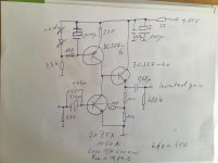
Concerning the Sony circuit I do not think that a differential amp is a good idea for a pre-pre.
It has 6dB more noise then a parallel symmetric design. They may have used it for other good reasons like low distortion and good DC precision. They use a massive 40mA idle though and in that time they had the great Toshiba, ROHM and Hitachi devices, long gone now, that combined super low Rbb with high and linear Hfe, plus high early voltage and low Miller capacitance. That where the days folks ! And I was just a child working with NE5534 and BC550,560.
It has 6dB more noise then a parallel symmetric design. They may have used it for other good reasons like low distortion and good DC precision. They use a massive 40mA idle though and in that time they had the great Toshiba, ROHM and Hitachi devices, long gone now, that combined super low Rbb with high and linear Hfe, plus high early voltage and low Miller capacitance. That where the days folks ! And I was just a child working with NE5534 and BC550,560.
There is another issue. Elcaps in older equipment may have aged due to heat. That makes the electrolyte dry out. No reforming can change that. So it makes good sense to replace them.
Yes, that gives a better sound but that does not explain that the new cap TYPE sounds better then the old one. That should require to use an NOS version to replace the old one and then comparing to other types.
Yes, that gives a better sound but that does not explain that the new cap TYPE sounds better then the old one. That should require to use an NOS version to replace the old one and then comparing to other types.
Joachim, yes, that was the reason I looked at replacing them, that they may have been dried out.
BTW These are the transistor types used in that prepre: 2SC1637 and 2SA872 .
BTW2 Some of us are still working with NE5534 and BC550, BC560. Like me ;-)
Jan
BTW These are the transistor types used in that prepre: 2SC1637 and 2SA872 .
BTW2 Some of us are still working with NE5534 and BC550, BC560. Like me ;-)
Jan
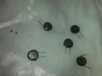
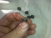
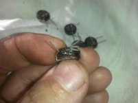
i wonder if this type of caps are the perfect cap for this application.these are the ones used as battery for memory dumps.220 000uf/5.5vdc although i have a feeling that the writing on themmight be wrong and the actual value is 22 000uf.still very high.I can't measure it anyway.
Attachments
I would think you don’t want any DC on a cartridge in that it may offset the stylus but I may be wrong.
Common wives tale. the generator in a cartride is too inefficient for a small current to move the coils. I'm not even sure I believe that the bias current could damage the windings either.
I am surely not knowledgable enough, but if that's the case why do some phone amps have the possibility to adjust the DC offset? (I was thinking of the Sony phono amp I have and the Hiraga PrePre)
Lots of new phono preamps have demag circuits built-in for just this: someone's been brave to pass DC current through their favourite MC 😛
Interestingly, people who probably understand the underlying physics like Mr VDH think it's much better to not magnetize the former in the first place.
Interestingly, people who probably understand the underlying physics like Mr VDH think it's much better to not magnetize the former in the first place.
- Home
- Source & Line
- Analogue Source
- coupling caps for phono prepre