Dear Forum Members!
Some questions about my calculations:
* How to measure the stray inductance of an output transformer:
1, With open secondary coil
2, With short-circuited coil
3, Closed with nominal impedance
* How do we calculate the lowest transferable frequency from the data received?
* How do we calculate the upper, critical frequency, the location of the break from the capacity data?
I have a finished 15-40Wos UL PP transformer and I would like to know approximately its properties.
Thanks to:
I
The pragmatic old school method I use (Primary inductance measurement):
1. Connect the output of an audio oscillator set for 50.0 mV at 70 Hz, across the
series circuit of the unknown inductor (L) and a variable resistance (R) connected
in series. Use (say) a 10K fixed resistor and a 5K pot in series for R. Adjust R
so that 25.0 mV appears across R when 50.0 mV is feeding the circuit.
Disconnect circuit and measure value of R.
2. Use this formula: 1.732 X R / 439.82 = L
The stray inductance can be divided into two parts:
1. The magnetic linkage between primary to secondary. This is dependent of the interleaving geometry, coil dimensions, turns number. This leakage makes a HF roll off with transformer loading and forms two kinds of resonances:
- with primary capacitance (series LC tank, peaking)
- with primary to secondary capacitance (parralel LC tank, dipping)
2. The ohmic resistance difference between secondary sections. The perfect transformer wants equal currents circulating in all secondary sections and when this does not happen, a specific leakage roll off occurs when loading the transformer.
I'm just giving some depth to the topic, because you might be measuring different values, depending of your transformer design and the fact if it's unloaded or not.
Last edited:
The folks at Omicron Lab have written a white paper on this topic:
https://www.omicron-lab.com/fileadm...ling/App_Note_Transformer_modelling_V_2_0.pdf
https://www.omicron-lab.com/fileadm...ling/App_Note_Transformer_modelling_V_2_0.pdf
OPT measurements
Salut All!
Thanks for your help!
I’m not an educated enough person, so I want to learn the simplest calculation.
I have one such instrument that measures inductance (capacitance) at 120 Hz and 1 kHz.
I have an insulation tester 1000V DC signal generator max. 6V RMS 0-5 MHz, oscilloscope 2x50 MHz, 5.5 digit complex desktop climber, frequency measure capacity, DC,AC, diode, etc.
With these instruments, how can I get the above results with the simplest calculations + measurements?
LCR merőműszer, induktivitas, kapacitas, ellenallasmerő Voltcraft LCR 4080 > inShop webaruhaz
Transformer: Parasitic parameters and equivalent circuit – European Passive Components Institute
The above article covers the inter-winding capacitance and leakage inductance
J&K Audio Design: Output Transformer Design
The above blog shows how to calculate high frequency roll off:
The high frequency limit can be calculated with respect to the leakage inductance and the normalized impedance, as follow:
Zn = (N1/N2)2 x Z2 + Z1
F2 = Zn / (2 * pi * L-leakage)
Transformers for Audio
This article warned on accuracy of inductance meter, so beware, and take care.
Last edited:
 Thanks to All the forum members for their help!
I just add that the primary inductance is level (and frequency) dependent. An OPT works with several hundred volts on its primary. I use the following method:
Connect the primary to an 1:1 mains isolation transformer that outputs roughly 230V. The secondary should be floating. Never connect the primary directly to the 230V mains power!
Measure the voltage and the current on the primary. Warning, the isolated voltage on the primary is still around 230V which is dangerous!
Now you can calculate the primary reactance using the XL = U / I formula. XL = 2 x PI x f x L
The stray inductance should be measured on the primary with the secondary short circuited, but with low voltage, like 5V.
As Icsaszar identifies, the primary inductance can be quite level dependant, so making a measurement at a very low signal level as in post #2 may be misleading, and similarly making just one reading at say 230Vac may also be misleading (and may be dangerous if there is not enough inductance). Many vintage manufacturers made measurements with 5 to 20Vac applied.
Primary leakage inductance is just one of a few parameters that define high frequency response. And the winding of concern can change depending on whether you are operating push-pull class A only and using the full primary winding, or if you are operating with only half the winding conducting such as can occur for class AB.
Both leakage inductance and shunt capacitance are the initial measurements needed. The actual response in an amplifier requires more details, including the driving impedance from the output stage valves and configuration, and the speaker side loading, as the frequency response becomes a complex filter whose cut-off frequency depends on all those parameters. Have you checked out Lee and his book on transformers, or other articles on making those measurements?
And UL operation brings in other performance issues that are typically not covered by the simple push-pull configuration assessment.
I'd suggest it may be a lot easier just to set up a test jig and drive your OT with a certain configuration (full or half-primary) and drive impedance, and with different loads to reflect back the PP impedance you may want to use, and plot the frequency transfer response for different drive voltage levels.
The folks at Omicron Lab have written a white paper on this topic:
https://www.omicron-lab.com/fileadm...ling/App_Note_Transformer_modelling_V_2_0.pdf
Please notice that the way interwinding capacitance C12 is measured is only useful for a transformer without any form of interleaving
Another measurement technique for the primary shunt capacitance is:
The plate-to-CT (P-CT) lumped shunt capacitance Cp is measured using an RC LPF -3dB frequency (F-3dB) test setup, where R is ~5x PP impedance and inserted in series with signal generator driving P-CT half-winding (the C of the low pass filter), with other P-CT open, and secondaries open and connected to CT and ground. For a constant signal generator voltage, measure the P-CT winding voltage, which should rise to a maximum in the kHz range, and then reduce the sig gen frequency back to where the primary winding voltage is 71% of maximum (ie. back to F-3dB). Then Cp is derived from the impedance at F-3dB using R and the frequency. The capacitance of the voltage measurement probe needs to be subtracted off the measurement result. The lumped capacitance seen by the driving plate can become 2x P-CT capacitance if other PP valve enters cut-off (class B operation).
The plate-to-CT (P-CT) lumped shunt capacitance Cp is measured using an RC LPF -3dB frequency (F-3dB) test setup, where R is ~5x PP impedance and inserted in series with signal generator driving P-CT half-winding (the C of the low pass filter), with other P-CT open, and secondaries open and connected to CT and ground. For a constant signal generator voltage, measure the P-CT winding voltage, which should rise to a maximum in the kHz range, and then reduce the sig gen frequency back to where the primary winding voltage is 71% of maximum (ie. back to F-3dB). Then Cp is derived from the impedance at F-3dB using R and the frequency. The capacitance of the voltage measurement probe needs to be subtracted off the measurement result. The lumped capacitance seen by the driving plate can become 2x P-CT capacitance if other PP valve enters cut-off (class B operation).
Last edited:
The best method is the reverse mode
OPT Characterization
In the diagram you can see the HV that can be omitted.
You need a minumum of test equipment.
I am preparing a new test set to measure more completely the OT
It will be shown in next weeks. It takes some time.
Walter
OPT Characterization
In the diagram you can see the HV that can be omitted.
You need a minumum of test equipment.
I am preparing a new test set to measure more completely the OT
It will be shown in next weeks. It takes some time.
Walter
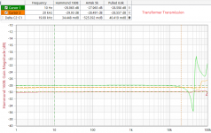
Some transformer measurements. The impedance peaks in the intrawinding measurements are used to calculate the interwinding capacitance.
Attachments
-
 Trafo_Comparison.png45.8 KB · Views: 270
 -
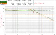 Trafo_PrimaryInductance.png66.1 KB · Views: 270
 -
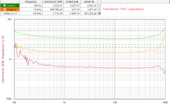 Trafo_Thru Capacitance.png47.7 KB · Views: 257
 -
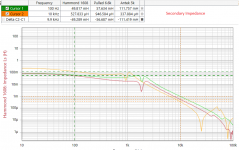 Trafo_Secondary Impedance.png61.5 KB · Views: 257
 -
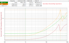 Trafo_SecondaryIntrawinding Capacitance.png45.8 KB · Views: 252
 -
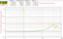 Trafo_PrimaryIntrawindingCapacitance.png55.8 KB · Views: 178
Last edited:
Just a very quick look at those graphs tells me:
I think some peak frequencies are indeed due to the winding distributed capacitance and / or the interwinding capacitances, versus the primary inductance.
Mid frequency peaks.
I think some peak frequencies are due to the Leakage Inductance, and the capacitances.
High frequency peaks.
Just my opinion from a 5 minute look.
Last edited:
to Jackinny
can you show the test set about your measurement?
In my opinion one of the heavy test to understand the quality of OT is the THD vs Frequency only of the trafo with a proper setup on lab
The shape of the curve tell us lot of things.
Walter
can you show the test set about your measurement?
In my opinion one of the heavy test to understand the quality of OT is the THD vs Frequency only of the trafo with a proper setup on lab
The shape of the curve tell us lot of things.
Walter
to Jackinny
can you show the test set about your measurement?
See post 4 -- link to Omicron's paper on trafo measurement.
But with 13 dBm max ( 1 volt) as test signal what do you think to see in a OT trafo?
If I have a OT in s.e. (= bias current) with a ratio of 20:1 to get 2,78 volt on 8 ohm (1 watt) I need around 55 volt on primary.
Which are the perfomances at low frequencies at that level as reference? It is only an example.
If I go to 8 watts the Vrms will be 160 Volt! What happen?
I have ready these tests with same windings and different nucleus ( for low frequencies) and also same nucleus and different windings ( for high)
In attach a THD vs Freq of a beautiful C trafo with Amorphous iron.
60 volt rms (171 volt p-p) on 750 ohm load ( as 300B Rp standard) around 5 watt rms.
Test set as described on my previous link.
3k5 primary, 8 ohm secondary. No bias current
The shape is very good; the thd stay under 0,1 % from 40 Hz to 25 kHz.
On the other test there is a frequency response at same level; at high we can see a trouble around 65 kHz but I consider it reasonable, this is due the parasitic components only.
And this is the trafo only.
I am preparing the test with I bias to know what will happen.
Walter
Attachments
- Home
- Amplifiers
- Tubes / Valves
- Completed output transformer measurements