Hello! I have taken the deep plunge into loudspeaker design and theory over the last several months. These forums have been invaluable to my growth in understanding. Thank You!
I have a puzzle regarding the measurements I obtained yesterday in my attempt to get raw driver readings with my new drivers in a test speaker cabinet.
In reading the thread "So you want to build your own speaker from scratch" I thought I was setting myself up for audio bliss and a deeper understanding of the science of acoustic measurement and engineering. I bought the test equipment (including the Dayton DATS v3 which gave results that agree very well with manufacturer spec) and have been practicing using 3 different crossover design software programs in anticipation of these measured results... These disappointing measurements when loaded into my crossover designers COMPLETELY change what needs to be done to achieve a flat response. So much so that I have very low confidence in the results.
Rather than trusting the measurements here I thought I would reach out and ask for some assistance on the causes of these anomalous results. If we finally determine the measurements are good... I have some serious questions on how to proceed with the crossover network development that I would love to talk about! But first I need help establishing confidence in the measurements and their interpretation.
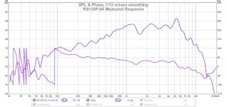
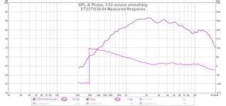
I chose these drivers because of their nice linear responses. The measured responses I got were FAR from linear. Below about 500 Hz I'm not really concerned due to the set up involved and the cabinet being ported out of the back. I did expect some baffle ripple effects (1K- 2.5K) and beaming. This is why I tested the drivers in a mock up test box with the actual baffle design and volume/ tuning I expect to use in the final version. So... now that I have a HUGE hump in the tweeter response and an extreme sloped response from the woofer how should I proceed? Starting a High Pass filter at 9K seems a little extreme... maybe it isn't... Please help!
The Results: I have included the REW graphs with 1/12th smoothing and phase. I am comparing these to the factory specifications also linked below.
The Measurement Setup:
---Laptop ASUS computer running REW
*headphone out to RCA jack set to "Speakers" mode
---Emotiva Mini-X A-100 Stereo Amp
---Pyle Microphone USB pre-amp
---DBX RTX-M omnidirectional measurement microphone
---Outdoors "Anechoic" measurement attempt
---Speaker on 7ft ladder with mic placement on center of driver 3 feet away
Drivers in Question:
Tymphany XT25G30-04: Direct signal sweep from 200 Hz - 20 KHz
https://www.parts-express.com/pedocs/specs/264-1016--tymphany-xt25tg30-04-spec-sheet.pdf
Dayton Audio RS150P-8A: Direct signal sweep from 20 Hz - 20 KHz
https://www.parts-express.com/pedoc...rs150p-8a-reference-series-specifications.pdf
The amplifier gain was unchanged as I switched between the drivers. I did not do a test with both operating concurrently.
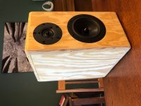
The Cabinet:
15 L with a 2" (51mm ID) port tuned to 49 Hz
Overall baffle measurements = 381 mm X 203 mm
The edge is a 1/2" (13mm) round-over
The tweeter offset 75 mm from both the left and upper edge.
I can include a baffle diagram if that would be useful.
Thank you so much for all of your help! I can't wait to have a deeper understanding of this fascinating subject.
OrionX76
I have a puzzle regarding the measurements I obtained yesterday in my attempt to get raw driver readings with my new drivers in a test speaker cabinet.
In reading the thread "So you want to build your own speaker from scratch" I thought I was setting myself up for audio bliss and a deeper understanding of the science of acoustic measurement and engineering. I bought the test equipment (including the Dayton DATS v3 which gave results that agree very well with manufacturer spec) and have been practicing using 3 different crossover design software programs in anticipation of these measured results... These disappointing measurements when loaded into my crossover designers COMPLETELY change what needs to be done to achieve a flat response. So much so that I have very low confidence in the results.
Rather than trusting the measurements here I thought I would reach out and ask for some assistance on the causes of these anomalous results. If we finally determine the measurements are good... I have some serious questions on how to proceed with the crossover network development that I would love to talk about! But first I need help establishing confidence in the measurements and their interpretation.
I chose these drivers because of their nice linear responses. The measured responses I got were FAR from linear. Below about 500 Hz I'm not really concerned due to the set up involved and the cabinet being ported out of the back. I did expect some baffle ripple effects (1K- 2.5K) and beaming. This is why I tested the drivers in a mock up test box with the actual baffle design and volume/ tuning I expect to use in the final version. So... now that I have a HUGE hump in the tweeter response and an extreme sloped response from the woofer how should I proceed? Starting a High Pass filter at 9K seems a little extreme... maybe it isn't... Please help!
The Results: I have included the REW graphs with 1/12th smoothing and phase. I am comparing these to the factory specifications also linked below.
The Measurement Setup:
---Laptop ASUS computer running REW
*headphone out to RCA jack set to "Speakers" mode
---Emotiva Mini-X A-100 Stereo Amp
---Pyle Microphone USB pre-amp
---DBX RTX-M omnidirectional measurement microphone
---Outdoors "Anechoic" measurement attempt
---Speaker on 7ft ladder with mic placement on center of driver 3 feet away
Drivers in Question:
Tymphany XT25G30-04: Direct signal sweep from 200 Hz - 20 KHz
https://www.parts-express.com/pedocs/specs/264-1016--tymphany-xt25tg30-04-spec-sheet.pdf
Dayton Audio RS150P-8A: Direct signal sweep from 20 Hz - 20 KHz
https://www.parts-express.com/pedoc...rs150p-8a-reference-series-specifications.pdf
The amplifier gain was unchanged as I switched between the drivers. I did not do a test with both operating concurrently.
The Cabinet:
15 L with a 2" (51mm ID) port tuned to 49 Hz
Overall baffle measurements = 381 mm X 203 mm
The edge is a 1/2" (13mm) round-over
The tweeter offset 75 mm from both the left and upper edge.
I can include a baffle diagram if that would be useful.
Thank you so much for all of your help! I can't wait to have a deeper understanding of this fascinating subject.
OrionX76
Attachments
If you're looking at academic reasons for the differences, there are many - one of which is that manufacturers use either infinite or IEC baffles, another being that LF responses are usually merged together, etc.
If you want to actually create a design, you need to take measurements of both drivers without moving the mic. In your case you will just have to choose a spot because your tweeter is not centered on the baffle, and you likely won't get a great listening setup that way. Ideally you want to be about 10 degrees off-axis from the tweeter
Then you need to take a second measurement with the mic 1cm away from the woofer dustcap, this is usually a LF sweep out to 1KHz. You then splice the resultant response around 450-500Hz with the result you got from your earlier sweep. You will see where the baffle effect begins to come in.
Just looking at it, you should get a good match between the drivers around 2.5-2.7 kHz. The drivers are well-chosen and the crossover should be easily doable, no issues at all.
There are some points to address.
First, you are measuring far field (correct), and doing so you will measure also the cabinet effects, notably the baffle step effect for the woofer, and diffraction (more for the tweeter than the woofer). Those effects add to the natural response of the drivers. Note however that baffle step and diffraction are basically the same thing.
Second, you need to do a gated measure. I don't know if REW is able to do it, as I use Arta (also free software for non commercial use).
Third, it seems your mic is not calibrated. No matter how a manufacturer claims that the mic is flat, the response will be flat only when a specific response graph will be provided and this graph will be used by the measurement sw in order to correct what is measured.
Ralf
Thank you for the quick responses!
I had considered getting a new mic that comes with a calibration file... sounds like that purchase will happen in near future. I had this sitting around from my live sound application.
The splicing of the woofer response curve is interesting. I was under the impression the outdoor measurements were as close to neutral as I could get. Is there a good thread on measurement best practices? I was indeed trying to see the baffle effects so that they could be taken into account. I guess I didn’t expect them to be so drastic!
I’m pretty sure REW can do a gated measurement. I’ll look into how.
Question on the offset tweeter. I did that to reduce the overall baffle effect between the two drivers... am i shooting myself in the foot with this arrangement? The baffle simulation seemed to show it working out well.
Thanks again!
REW can do gated measurements. It doesn't do conventional timed measurements unless you use two channels.
Your baffle offset is the least of your concerns just at the moment. If you're just after an opinion I would have kept it in the middle and rounded the cabinet edges instead, but the difference isn't going to appear significant on these response measurements anyway.
Your baffle offset is the least of your concerns just at the moment. If you're just after an opinion I would have kept it in the middle and rounded the cabinet edges instead, but the difference isn't going to appear significant on these response measurements anyway.
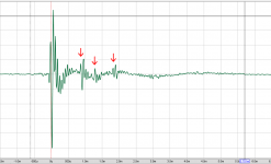
First, you need to line up the beginning of the impulse. Until you learn to do that by hand, the easy way is to click on 'controls' at the top right and 'estimate IR delay'.
The 'IR windows' button is on the top row. Change the right window time and 'apply windows'.
You will want to learn to estimate your available reflection free time and your desired minimum window size because these are usually in competition. This also means you should probably learn to visually detect reflections on both the response plot and the impulse.
Attachments
Excellent. I will dig into the REW features and take another set of measurements shortly. I hope to have a set of good measurements by the end of the week... busy with a new job I’m very greatful for. It’s rough out there in the job market right now.
I should be able to post results and progress by Friday afternoon. I’m really enjoying learning about this topic! Thanks again everyone, for the help.
I should be able to post results and progress by Friday afternoon. I’m really enjoying learning about this topic! Thanks again everyone, for the help.
Just looking at the tweeter response, something is amiss. No matter what the baffle geometry I would not expect to see that much difference between the manufacturer curve and what you have measured. Also for a non flat response, the phase looks remarkably flat...
The dayton graph looks like it is more in line with the manufacturers response (in the higher registers), but I wonder about your tuning, maybe you have some major leaks? Output seems to be way further down than baffle step alone should account for.
edit: doing a quick sim in unibox, 15L seems a bit big for this woofer, is that the actual space available (minus port volume and speaker displacement/bracing) or the size available to the woofer. There is about a 2db droop from the box tuning, 10L tuned to around 53Hz is a lot flatter, and has a somewhat better transient response. Perhaps try putting something in the box to reduce the volume somewhat and see what effect that has.
Tony.
Last edited:
Thanks Tony! I agree the tweeter response was the most unnerving. The box according to my calculations should be about 15L (minus a non-existent theoretical crossover of 0.2 liters) with current load out.
My goal here is to gain understanding of my results (software, best practices...everything) so that I can build, test, repeat. I’m here to learn... hopefully from real experience and this community’s help, how to test and approach design efficiently and correctly.
My goal here is to gain understanding of my results (software, best practices...everything) so that I can build, test, repeat. I’m here to learn... hopefully from real experience and this community’s help, how to test and approach design efficiently and correctly.
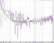
I put the dayton factory response into vituix cad and did a quick estimate of the position of your woofer on the baffle, the result is attached. The trend for the baffle step is similar to what your measurements show but I think perhaps your measurement is up to 4db lower than the sim would predict at 100Hz and even more at 50Hz.
The tweeter response looks a bit more like the 30deg off axis measurement than the on axis.
Could you post a pic of your measurement setup as well. All sorts of things which may seem minor, can have an effect on the measurements. A nearfield measurement of the woofer (like 5 - 10mm from the dustcap) would also be informative. It will be lower than overall output due to not having port contribution, but it should give a reasonable idea of the flatness (or otherwise) of the woofer in box.
Tony.
Attachments
For beginners, here is the go to paper on in-room measurements by Jeff Bagby: Box
You will also need to account for the drivers' acoustic centers:
Box
This is based on Jeff's PCD but the method can be adapted to other software like XSim too (actually it's simpler in XSim as you don't need to worry about the x and y coordinates).
And for blending near and far field measurements:
FRD Blender and Minimum Phase Extractor
jReave, Thank you! These papers were very helpful. This is the content I am here for.
I can see that getting accurate measurement results with these methods is a blend of pure theory/ mathematics and technical skill. I love deep dives into subjects like this!
I am starting to see several parallels to optics and the measurements involved when creating/ measuring optical systems. I ran an optical lab for 6 years in a previous life.
Again, my thanks to everyone for all of the help!
I was planning to leave this until later, but if your measurement program does timing you should go with the measured phase. REW will do timing, as I'll show below (*)the drivers' acoustic centers:
Regarding JBs second paper - Box
It struck me as odd that Jeff would be looking to find driver offsets. However the paper shows that the software he used at the time was not capable of timing. I double checked I wasn't overlooking a feature of his PCD software and it states that - "Without knowing this value phase relationships will not be accurate," Therefore it's clear that Jeff is talking about single point measurements and not a three-dimensional model, so the offset doesn't need to be known explicitly.
If you can't avoid modifying to minimum phase, it can introduce errors. Excess phase is useful information in speaker design, and reducing to a minimum phase version of phase suppresses this and brings it up as something different. To show this I have taken a screenshot of an at hand measurement with and without doing this - one showing excess phase and one, excess group delay, and how they will not line up by adjusting normal delay.
* REW uses two channels to time measurements. One is looped back as a reference and one handles the test signals. The premise is that the data may take time through the computer, but side by side the channels hold the reference. You can loop through the test amplifier or just the sound card, the reaction time for the electronics is virtually instantaneous either way, the but you might then need to attenuate the looped signal.
Attachments
Allen, the conclusion I came to with PCD was that you could use it just using measurements with relative phase offsets incorporated provided you did not enter in any offset information in PCD itself.
But if you want to do the off axis modeling that PCD can provide, then you need to use minimum phase measurements and put in all of the relevant offsets.
Tony.
But if you want to do the off axis modeling that PCD can provide, then you need to use minimum phase measurements and put in all of the relevant offsets.
Tony.
Last edited:
Indeed.you could use it just using measurements with relative phase offsets incorporated provided you did not enter in any offset information in PCD itself.
If I understand, you're saying that timing would be left at zero for each driver and offsets would be simulated. I agree that these areas need to be accounted for in one way or another.But if you want to do the off axis modeling that PCD can provide, then you need to use minimum phase measurements and put in all of the relevant offsets.
A speaker system measurement is not just made up of minimum phase plus delay components. This is shown in the fact that there is excess group delay. As for Jeffs apparent acquiescense that it may not be so, I might point out at the least that he was operating under limiting conditions at that time. Adjusting delay does nothing more than change where the impulse start point gets registered.
Attachments
As always it is just a sim, and will have inherent limitations. I only ever used it for quick visual feedback changing values in a crossover, to get in the ball park, and then switched to speaker workshop to do my final crossover modeling (using measurements with relative phase built in).
More recently I looked at vituix cad and multiple off axis measuerments, but I know you have some reservations about that too 🙂 You are way ahead of me in understanding of the limitations Allen! 🙂 I'm generally happy if I can get a good correlation between simmed response on axis compared to the actual measured response of the realized crossover.
Tony.
I'm currently using VituixCAD, Xsim, and Passive Crossover Designer. Trying to find the one I want to stick with. So far I think all three have their advantages and disadvantages. I am planning on using the off axis measurement features in VituixCAD as soon as get my technique down. It sounds like there might be some concerns here... Any special measurement considerations with the VituixCAD off axis approach? I am in the midst of setting up for measurements now.
Are there other programs you would reccomend?
Are there other programs you would reccomend?
The crossover circuit itself is one dimensional (signal in/filter/signal out). In this respect, if you already know what you need then one simulator is as good as another. Calculation accuracy for the circuit itself is not really a concern. I'd be basically content using any of them if that's what I happened to have on hand.
Directivity is different horizontally and vertically and everywhere in between due to the crossover physical aspects. I like to build in unconventional spaces (such as corners), I haven't found a speaker design program who's acoustic concerns are 'general purpose' enough to be of use in all situations.. I'd need to learn the limitations through trial and error, remain mindful of them and keep up with the changes, and that gets difficult at this level. Given that I'm accustomed to working with CAD, and pencil and calculator and microphone, I'm thankful for the freedom.
I do have a soft spot for a number of them though for a subset of their talents.. Speaker Workshop for its ability to do operations on traces and to display traces, Akabak for its ability to sim Synergy speakers, VituixCad for its plot tracing tool converting screenshots into files and for some of the sims I do for others here, and hornresp.exe for its horn abilities, directivity and wavefront abilities, I also use Xsim here for demonstrations and examples as many go that route and can relate.
Another pitfall for new hands is that some speaker design software offers different options for different methods. For example you can set driver offset in the sim, or measure it. Some newcomers do both because it is there and it looks like it should be used, and the result is not correct.
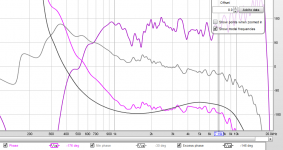
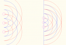
Absolutely. Too much info can be difficult as well. I'd only sim lobing in the design phase and without measurements to show the lobing itself. For instance, the attached (admittedly simplistic) image shows how it can be useful to see what 1/2 wavelength spacing is like compared to 1 wavelength.As always it is just a sim,
At crossover time, either way simulating from a pair of measurements will only be approximate because no matter what you do with phase, there are positional issues. There is only one person I'm aware of on this site that may have reverse engineered diffraction from a set of polar measurements but fortunately measuring can get the same end result.
Attachments
Well... My second attempt at measurements was more successful. I learned a bit more about the windowing features in REW but I am still getting unexpected and inconsistent results. I started using the built in acoustic timing with REW that led to more uniform results.
I have decided to purchase a new digital interface for the loop back timing function (will also be fun to record some tunes with my kids!) and a mic with a set of calibration files. My microphone was giving different results when pointing directly at the source and when at 90 deg.
Focusrite Scarlett 2i2 3rd Gen
Dayton EMM-6
Interesting that REW doesn't seem to have a function to use pink noise for measurement but relies on a frequency sweep.
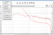
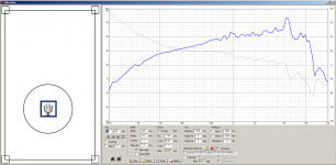
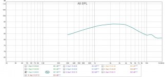
I am still getting what I consider an unexpected and aggressive roll off in the high frequencies. I even tried doing a near field measurement just off the waveguide cone of the XT25TG30-04 (Shown Below). This tweeter is supposed to be laser flat out to about 15K Hz but all of my measurements show this roll off around 4K. I'm starting to think it has more to do with my equipment. Worried that my headphone jack is the culprit... Any thoughts on how to best test this hypothesis?
I have decided to purchase a new digital interface for the loop back timing function (will also be fun to record some tunes with my kids!) and a mic with a set of calibration files. My microphone was giving different results when pointing directly at the source and when at 90 deg.
Focusrite Scarlett 2i2 3rd Gen
Dayton EMM-6
Interesting that REW doesn't seem to have a function to use pink noise for measurement but relies on a frequency sweep.
I am still getting what I consider an unexpected and aggressive roll off in the high frequencies. I even tried doing a near field measurement just off the waveguide cone of the XT25TG30-04 (Shown Below). This tweeter is supposed to be laser flat out to about 15K Hz but all of my measurements show this roll off around 4K. I'm starting to think it has more to do with my equipment. Worried that my headphone jack is the culprit... Any thoughts on how to best test this hypothesis?
Attachments
- Home
- Loudspeakers
- Multi-Way
- Anomalous REW driver readings? 2-way design help!