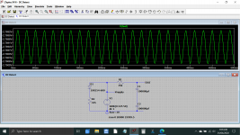
.......With simulation can you read the dc voltage at the test point?
ps= maybe the definition dc over ac is not properly right 🙂
Walter
Not as a number, no. The simulation contains no DC voltage source, it is purely a real time AC simulation... however we can do a couple of things.
1/ We can make the caps much larger, here they are 100,000uF. The time constant is T=CR which is 50,000uF*15k giving 750 seconds.
2/ We can now run the simulation for a lot longer time period. Now its running for 20,000 seconds of data (so way over the time constant of the caps) and only saving the last 500ms of that data.
Now we can see that although the trace still shows a slight downward trend, the reading is actually very constant. Look at the scale. Its not changing much at all. So the DC value is pretty much what you see... about negative 2.79 give or take.
Its difficult to know what value to put on the simulated diode load because everything depends on the supply source impedance and how much the supply falls under load. Here at home I see around (from memory) a 0.4V drop per killowatt loading at 230 VAC (closer to 240 and higher at times).
Attachments
I read the first 10 or so pages before commenting here, apologies if some of this stuff has been pointed out.
First I think this is a very worthwhile topic to discuss.
Second I would like to discuss some of Rod Elliott's points regarding DC blockers here Mains DC and Transformers
1) We need capacitors with decent ripple current ratings, in Rod's application he designed for an amplifier but I feel the DC blocker should be designed for the full current rating of the mains wiring (that's 10A for domestic applications in Australia) and some head room for safety let's just call it 12A
2) You basically want the smallest capacitors to do the job (as you will see these will still be large) since many DC events are often random/intermittent, to quote Rod exactly : "Excessive capacitance may be as bad as too little, because the charging time is so long that many of the DC 'events' may not last long enough for the caps to charge and remove the DC component."
So if we go back to Rod's example but allow for 12A instead of 500mA and to quote rod again "Keeping the RMS voltage across the capacitor below 1V would seem like a reasonable figure"
Then Xc will be 1/12 not 1/0.5 that he suggested for a single component Class AB amp.
C=1/(2 x Pi x F x Xc)
= 1/(2 x3.142x50x(1/12))
= 38,197uF
So we would essentially need 2 x 76,000uF (or 82,000uF) caps in series, assuming we wanted to plug a power board into this blocker and run all of our equipment off it.
Going to digikey
This capacitor meets these requirements
Blocked
If there is a very dumb mistake with the calculations or interpretation of Rod's notes let me know.
I don't want a dc blocker for ever bloody component, I think for safety it is best to design for the full rating of the mains power outlet in your home and then run a power board from the blocker.
If the mains wiring has a resistance of 0.1 Ohms then the time constant for 2 x 82,000uF capacitors in series will be .1 x .041 = 0.0041 seconds, hope that is a fair assumption.
Last edited:
I wonder whether the "caps are too big" problem can be seen in simulation, i.e., Good behavior in simulation with smaller caps but Not As Good behavior in simulation with bigger caps. I hope it's not a situation where one must accept Rod's claims & assertions as undisputed truth, because simulation is impossible / misleading / unacceptably imprecise.
Also, the descriptive language sounds quite strange.
"The DC event may not last long enough" seems like it could be self contradictory. By the very definition, a "DC event" must last forever, i.e., its period must be infinity and thus its frequency must be zero Hertz. 0 Hz == DC.
It may be true that a certain range of pulse widths, superimposed upon the 50 Hz sinusoidal mains waveform, do or do not get passed straight from the input to the output. But I wouldn't call them "DC events", myself.
I wonder whether the "caps are too big" problem can be seen in simulation, i.e., Good behavior in simulation with smaller caps but Not As Good behavior in simulation with bigger caps. I hope it's not a situation where one must accept Rod's claims & assertions as undisputed truth, because simulation is impossible / misleading / unacceptably imprecise.
If the time constant for 41,000uF on mains wiring is 3/5 of FA (<0.01 seconds), then maybe his idea of large capacitors is a lot bigger than my idea of large capacitors.
My feeling with Rod, is that he is so cynical and jaded by so much bs that is out there, he often then takes an extreme opposing view which is not actually right either.
Last edited:
Anyway, I think I will build this, as well as incorporating filtering, then actually see if I can see any improvement with the noise floor at the output of one of my amps using a keysight distortion analyzer.
Does anyone know what the lowest frequency we are permitted to filter down to?
Is 5kHz ok?
I noticed while testing power supplies that applying a 5kHz low pass filter on the scope removed what appeared to be around 90% of the high frequency noise that was on the ripple.
Does anyone know what the lowest frequency we are permitted to filter down to?
Is 5kHz ok?
I noticed while testing power supplies that applying a 5kHz low pass filter on the scope removed what appeared to be around 90% of the high frequency noise that was on the ripple.
Last edited:
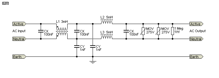
Here is an example of a mains filter.
Does anyone have any ideas or opinions regarding improving it further.
Does anyone have any ideas or opinions regarding improving it further.
Just a thought 🙂 you could specify the resistor more completely in case anyone builds it.
The wattage isn't very important here as even a 100mW rating would cover it dissipation wise but what is absolutely critical is the voltage rating of the part used. Time and time again I've seen parts that outwardly seem OK fail on this point. It's mission critical.
Two series 470k's (again high voltage) might also be an option. These HV parts are surprisingly available in SMD outline if required as well as conventional through hole.
I prefer to install the MOVs as far upstream as possible: AC plug, fuse, switch, MOV ... then rest-of-circuitry. If you use a fast-blow fuse (which you can do if you have inrush current limiting) then during a mains surge, the MOVs convert the high voltage surge into a clamped-voltage, enormous current, which blows the fuse immediately. And if you don't use a fast-blow fuse, you still have a fighting chance to confine most or all of the damage to the fuse.
A "2.5 ampere, slow-blow" fuse pops in 10 milliseconds if you push 100 amperes through it, according to this fuse datasheet
While this 275V Metal Oxide Varistor is rated for ten thousand amperes of surge current, and 303 Joules of dissipation energy.
Sounds like a fighting chance.
A "2.5 ampere, slow-blow" fuse pops in 10 milliseconds if you push 100 amperes through it, according to this fuse datasheet
While this 275V Metal Oxide Varistor is rated for ten thousand amperes of surge current, and 303 Joules of dissipation energy.
Sounds like a fighting chance.
Yep MOVs upstream makes entire sense
Never used these before but they could be ok http://www.mouser.com/datasheet/2/622/Cosel_NBHseries-1215896.pdf
Never used these before but they could be ok http://www.mouser.com/datasheet/2/622/Cosel_NBHseries-1215896.pdf
Just a thought 🙂 you could specify the resistor more completely in case anyone builds it.
The wattage isn't very important here as even a 100mW rating would cover it dissipation wise but what is absolutely critical is the voltage rating of the part used. Time and time again I've seen parts that outwardly seem OK fail on this point. It's mission critical.
Two series 470k's (again high voltage) might also be an option. These HV parts are surprisingly available in SMD outline if required as well as conventional through hole.
Good point
Here is an example of a mains filter.
Does anyone have any ideas or opinions regarding improving it further.
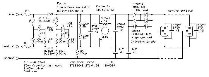
Here is how my filter is made:
I don’t believe paralleling MOVs make much sense due to their tolerances.
As soon as one of the MOVs starts conducting, the others are out of the race.
As soon as one of the MOVs starts conducting, the others are out of the race.
Do these MOV suckers have a temperature coefficient that lends itself to this kind of effect like an NTC inrush current limiting device?
Do they switch on hard or is it a gradual smooth turn on.
Having an additional as back up if one fails is probably not so bad though.
Do they switch on hard or is it a gradual smooth turn on.
Having an additional as back up if one fails is probably not so bad though.
Last edited:
Here is how my filter is made:
This looks quite nice, just checking it over.
Do these MOV suckers have a temperature coefficient that lends itself to this kind of effect like an NTC inrush current limiting device?
Do they switch on hard or is it a gradual smooth turn on.
Having an additional as back up if one fails is probably not so bad though.
A temperature coefficient is not specified in the datasheets that I saw.
The switch on hard and have a very low impedance within nanoseconds.
Yes a second MOV as backup cannot hurt...
In some applications a ground-wire-choke could make sense, since the ground itself carries more and more noise.
Put that choke at the output of the filter to isolate it from the mains-noise. I have not tried it myself yet but I'm planning to upgrade my filter with it.
DENO - Ground wire choke, open design
Put that choke at the output of the filter to isolate it from the mains-noise. I have not tried it myself yet but I'm planning to upgrade my filter with it.
DENO - Ground wire choke, open design
Regarding Mindutis' circuit:
Wouldn't it be preferable to remove DC first before filtering rather than last?
Wouldn't it be preferable to remove DC first before filtering rather than last?
I don’t believe paralleling MOVs make much sense due to their tolerances.
As soon as one of the MOVs starts conducting, the others are out of the race.
If the surge is super powerful and manages to destroy the first MOV, the second one takes over. When the second one is destroyed, the third one takes over. Etc.
- Home
- Amplifiers
- Power Supplies
- DC blockers and mains filters