Hi all,
as a next project I was thinking of trying my hand at something not too elaborate, possibly SE class A (eg with EL34, 6p3s, 6L6, etc.). Any suggestions about it?
The aim is a good quality speaker amp (not necessarily "top" though) in the range of 5-10W about.
I have found previous threads dealing with 12AU7 SRPP / EL34 that I might be interested in. The recently rewound transformer usable for this purpose has 150VA with sec. 285V / 200mA, 6.3V / 5A and 5V / 2A. Thanks.
5 W. and SE = easy! Full pentode mode "12" W. multi-grid type with regulated g2 B+. A single 12AX7/ECC83 or "equivalent" type is all that's needed in the small signal dept., for both channels.
The Russian 6Π15Π-EB (6p15p-ev) is an interesting possibility. A single 0A2 gas discharge regulator neatly takes care g2 regulation. BTW, sockets correctly wired for the 6Π15Π accept EL84s, without incident.
The Russian 6Π15Π-EB (6p15p-ev) is an interesting possibility. A single 0A2 gas discharge regulator neatly takes care g2 regulation. BTW, sockets correctly wired for the 6Π15Π accept EL84s, without incident.
Good suggestion. Russian power tubes it's what I thought first indeed. I already used some other type of them with very good results (OTL). They are cheaper that EU/US equivalent tubes but equally good.
As rectifier tube from my collect I would have a unfamiliar british IW4-350. Could it have a practical use with that?
As rectifier tube from my collect I would have a unfamiliar british IW4-350. Could it have a practical use with that?
As rectifier tube from my collect I would have a unfamiliar british IW4-350. Could it have a practical use with that?
That rectifier should work, providing you can get appropriate heater voltage. Capability (120 mA.) seems to be reasonably close to the suitable 5Y3. A 10 μF. 1st filter cap. and 10 H. choke feeding a 120 μF. reservoir part seems to make an adequate B+ PSU.
I believe that the 6P14P would suit far better than the 6P15P, which has a reduced screen voltage rating.
6P3S is something I am working on myself, but I feel it will not make 5W. Maybe 3 or 4 clean Watts.
6P3S is something I am working on myself, but I feel it will not make 5W. Maybe 3 or 4 clean Watts.
I believe that the 6P14P would suit far better than the 6P15P, which has a reduced screen voltage rating.
Actually, increased screen grid density, for better linearity.
Actually, increased screen grid density, for better linearity.
Well...I have not used either valve, and the '15 may well be more linear than the '14. (As far as a TV scan tube need to be linear)
The screen, from datasheet at least, seems a great deal more fragile. Not a problem, if one enters the project with eyes open, but certainly 6P14P and 6P15P aren't necessarily interchangeable.
Not quite, but almost the same feeling I have for 6P3S vs 6P3S-e - I'll stick to the 6P3S thanks
Last edited:
Have a look here for another idea Vinyl Savor 6CB5A SE Amps?
Mona
It's an interesting project. I can see the OPT should be not so small though, chosen at least 50 mA (I read 70mA on schematic). My further problem for that is the psu, I can't reach 400V at B+ (sec. has 285VAC).
I believe that the 6P14P would suit far better than the 6P15P, which has a reduced screen voltage rating.
For ultra-linear (UL) mode the EL84 and its equivalents is clearly better than the 6Π15Π. However, full pentode mode exhibits maximum open loop linearity, when g2 B+ is regulated at a fraction of anode B+. The 150 V. g2 limit of the 6Π15Π is advantageous in combination with a 150 V. 0A2 gas discharge regulator. When g2 is regulated at 150 V. and anode dissipation is carefully/ruthlessly held <= 12 W., mildly exceeding the published anode voltage limit is safe. Heat, not mere volts, is the destroyer of tubes.
After getting full pentode mode 6Π15Π "finals" working well, "rolling" EL84s in can be tried. Repeat, sockets correctly wired for the 6Π15Π accept EL84s, without incident.
Eli,
I understand that linearity is best with screens regulated.
What fraction of anode volts?
However, I dont see how the '15 regulated at 150V is "better" than the '14 screens regulated at 200V.
Other than the inherent linearity/non linearities due to geometry of the internals.
In my small experience, I have noted that actually linearity is best when screen volts are elevated.
E.g. for 6P30BR, with anode at 300V, screen at 250V.
So 5/6ths HT meets the screen.
At 150V screen the THD performance is an order of magnitude worse.
6P30BR is listed as Receiving tube/Video amplifier and not TV line scan, so perhaps that is where the difference lies?
Max. "rolling" flexibility is obtained setting up for the 6Π15Π.
Have intermodulation distortion (IMD) measurements been made? Being unrelated to the fundamental, IMD is highly irritating. Regulating g2 B+ at a fraction of anode B+ definitely holds the IMD down.
The published limits, especially g2 fragility, pretty well control how the 6Π15Π gets set up. FWIW, I suspect experimental determination of what works "best" with each type is necessary. The g2 voltage ultimately settled on could easily be a compromise between open loop THD and open loop IMD. In any event, loop NFB of some kind is needed in combination with full pentode mode "finals", if only for damping factor reasons.
That rectifier should work, providing you can get appropriate heater voltage. Capability (120 mA.) seems to be reasonably close to the suitable 5Y3. A 10 μF. 1st filter cap. and 10 H. choke feeding a 120 μF. reservoir part seems to make an adequate B+ PSU.
Ok thanks. Yes, I already have a secondary output equipped for 4V.
Regarding the idea, I had some options in mind that I've seen around, which I report below:
Друг | VT52.com
RH Amplifiers: RH84 amplifier - revision 2
DECWARE - Zen Taboo designer's notes (it seems a commercial brand though)
And this one on y.tube built with very good components (maybe out of my reach):
KT88/EL34... Single Ended Tube Amplifier Build - YouTube (I think the schematic is from here: https://www.sb-lab.eu/single-ended-el34/)
JMO, adhere to the KISS (keep it simple stupid) principle. A 12AX7 section voltage amplifier cap. coupled to a "12" W. multi-grid power "final". A "simple" GNFB loop around the entire setup and reasonably competent O/P "iron" round things out.
Obviously, shipping between New Mexico, U.S.A., and Italy is a bad idea. However, something electrically similar to Edcor's GXSE15-5K sourced closer to home will be fine.
Obviously, shipping between New Mexico, U.S.A., and Italy is a bad idea. However, something electrically similar to Edcor's GXSE15-5K sourced closer to home will be fine.
'Tubelab' George's SSE amp design is also in this ballpark, using 12AT7 and 6V6, EL34, 6L6, etc.
Tubelab SSE Board | Tubelab
Another interesting possibility might be to use a pentode driving an 6P14P or 6P15P with shunt ("Schade") feedback from plate to grid of the 6P15P. But that is more complex...
Tubelab SSE Board | Tubelab
Another interesting possibility might be to use a pentode driving an 6P14P or 6P15P with shunt ("Schade") feedback from plate to grid of the 6P15P. But that is more complex...
However, for 5-10W SE amp 6P15P nor 6P14P is not sufficient. I would recommend EL34, or 6550. Sweep tubes like 6CD6, for example.
Edelweiss-3 with 6550
Edelweiss-3 with 6550
The RH amps (like RH84) stirred up a bunch of controversy here a few years ago. Basically, that is the shunt feedback idea, but with an ECC81 (12AT7) as the input tube. As was pointed out back then, the shunt feedback idea relies on the high gain, high anode resistance *and* fairly high current drive capability of a pentode to properly drive the feedback loop. Any triode (ECC83 or ECC81) is going to have limited gain compared to a pentode, or will have low anode resistance (ECC81), or will have limited current drive capability (ECC83).
Member reVintage came up with a few examples of this kind of SE pentode amp with shunt feeback. Like this one:
Use EF184 for 6EJ7 and use 6P14P or 6P15P for EL84.
Adjust value of R12 to get about 225V at g2 of 6P14P, or 150V at g2 of 6P15P.
Member reVintage came up with a few examples of this kind of SE pentode amp with shunt feeback. Like this one:
An externally hosted image should be here but it was not working when we last tested it.
Use EF184 for 6EJ7 and use 6P14P or 6P15P for EL84.
Adjust value of R12 to get about 225V at g2 of 6P14P, or 150V at g2 of 6P15P.
Last edited:
Yes, I had put an eye to EL34 SE and it's great, the problem (apart other components) is that I would use the transformer I already own and I fear it's not enough for it.
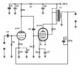
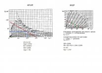
The suggestion by Rongon seems interesting, but I'm not sure to want to use "full" pentodes set-up. Meantime I tried to draw something with 6n2P and 6p15p from datasheet. I don't know if can be ok...
The suggestion by Rongon seems interesting, but I'm not sure to want to use "full" pentodes set-up. Meantime I tried to draw something with 6n2P and 6p15p from datasheet. I don't know if can be ok...
Attachments
Last edited:
Because of 6Π15Π g2 fragility, R7 in that setup needs to be 1 Kohm.
Bite the bullet! 😉 Wire those fragile screen grids to the 150 V. obtained from a 0A2 gas discharge regulator. A greater % of the O/P voltage has to be fed back, when full pentode mode is employed, than is the case when ultra-linear or triode mode is used. However, full pentode mode has additional gain that "rides to the rescue". 🙂
5 W. from a full pentode "12" W. multi-grid power type is quite reasonable. Triode is good for 2 W. 🙁 UL will struggle to reach an honest 5 W.
Triode wired "12" W. multi-grid types are very nice. Unfortunately, high sensitivity speakers are a must, given the small amount of power produced.
- Home
- Amplifiers
- Tubes / Valves
- Idea for a SE tube amp 5-10W