They are tricky, but worth the effort.
Get yourself a MC and make the most of those Fets!
That's the plan 🙂
Leds will only light up if you switch it into MM mode.
What about the other issues with high HT?.. Any suggestions on best way to reduce this? If I had a schematic I could determine on my own, but I must ask for assistance with this instead, sorry for more questions.
Also, curious about the 2.7V on cathodes of V1.. Shouldn't that just be fixed to 2.1-ish volts no matter what (due to using the red LEDs)?
thehoj, fit a 1.5M ohm resistor across C5P and then re-measure your voltages.
It does seem rather high on V1 cathodes, I guess you have red Led's?
It does seem rather high on V1 cathodes, I guess you have red Led's?
Okay, I will try that.
These are the LEDs I used. 151031SS04000 Wurth Elektronik | Mouser Canada
Should I use something different. The document said virtually any red LED was okay. Is there a specific recommendation that you could make from Mouser?
Thanks!
These are the LEDs I used. 151031SS04000 Wurth Elektronik | Mouser Canada
Should I use something different. The document said virtually any red LED was okay. Is there a specific recommendation that you could make from Mouser?
Thanks!
thehoj, fit a 1.5M ohm resistor across C5P and then re-measure your voltages.
It does seem rather high on V1 cathodes, I guess you have red Led's?
This fixed the issue with the voltage. It's right where it should be now.
Unfortunately somehow I wrecked the pads on the cathode for my LD1R LED. Could someone tell me what this connects to? Is it just to ground? I think I will need to run a wire directly to wherever it needs to go.
Can you put a picture up of what you've done please....This fixed the issue with the voltage. It's right where it should be now.
Unfortunately somehow I wrecked the pads on the cathode for my LD1R LED. Could someone tell me what this connects to? Is it just to ground? I think I will need to run a wire directly to wherever it needs to go.
It'll be really hard to see in a picture because I kind of mangled up the cathode pad on LD1R, but basically I had unsoldered the LED's when I thought I had them in backwards, and on one of them the actual pad came off when I was taking out the LED.
So now there is nothing for the solder to adhere to on the cathode pin of LD1R. Looking at the PCB it seems like that pad is just going to ground, so I thought maybe I could just wire it with a little piece of wire directly to ground. I'll try to get a picture.
So now there is nothing for the solder to adhere to on the cathode pin of LD1R. Looking at the PCB it seems like that pad is just going to ground, so I thought maybe I could just wire it with a little piece of wire directly to ground. I'll try to get a picture.


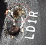
Holy crap!!!!!Ugh.. It looks so brutal up close.. But there's no pad there for the cathode to solder to.
How did you do that?
Yes, looks like it goes to ground....
Just checked the PCB with a multimeterView attachment 872264View attachment 872265
Hm.. Wait a minute, what is the polarity of the LED? Is the cathode going to the square or circle pad? I had thought the cathode was on the circle pad. That's how I have it wired on the other one, and it lights up. Is it Anode to ground and cathode to that pin on the relay?
Check the other one....it'll be the sameHm.. Wait a minute, what is the polarity of the LED? Is the cathode going to the square or circle pad? I had thought the cathode was on the circle pad. That's how I have it wired on the other one, and it lights up. Is it Anode to ground and cathode to that pin on the relay?
What the crap.. Did I still do this wrong? Man this is frustrating, I meticulously soldered everything else perfectly, and somehow screwed up this one little thing that is messing with me.
The two LED's are mirrors of eachother aren't they. I can't even tell which is square and circle anymore.
The two LED's are mirrors of eachother aren't they. I can't even tell which is square and circle anymore.
Hang on...What the crap.. Did I still do this wrong? Man this is frustrating, I meticulously soldered everything else perfectly, and somehow screwed up this one little thing that is messing with me.
The two LED's are mirrors of eachother aren't they. I can't even tell which is square and circle anymore.


Check the other one....it'll be the same
Okay, so they do go in in opposite orientations. Square pad is facing away from the terminal blocks for LD1L, and it's facing toward the terminal blocks for LD1R.. Ugh. So it's the circle pad that I've screwed up on LD1R.
So I need to reverse the LED again, and would it be safe to say that this is where I should run a wire?
Attachments
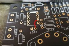
That's where the track goes, so I'd have thought so..Okay, so they do go in in opposite orientations. Square pad is facing away from the terminal blocks for LD1L, and it's facing toward the terminal blocks for LD1R.. Ugh. So it's the circle pad that I've screwed up on LD1R.
So I need to reverse the LED again, and would it be safe to say that this is where I should run a wire?
Hm.. I tried that and neither of them light up now. I wonder if that pad goes to another point.. It's hard to tell on the other side of the PCB. Do you have any close ups of that circle pad on both sides where you can see the traces?
Is there any way I could see just that portion of the schematic? I know we can't see the whole thing, but maybe just that part?
Is there any way I could see just that portion of the schematic? I know we can't see the whole thing, but maybe just that part?
- Home
- Source & Line
- Analogue Source
- Bigbottle Phonostage Builders thread