R3 is the MM load resistor.
Change to whatever you need, 39K is the closest to 40K.
Ohh Okay. So I don't need to add additional resistive load into LoadR and LoadL then.. I will use a 39K and if need to bring it up, I can add at the plugs. Makes sense.
On another note, looking at the BOM, I see there is no Mouser part number for C6L & C6R. I know this needs to be 1% tolerance, but does this need to be a 160VAC/250VDC part?
Or could I use this 100VAC/160VDC part? MKP1837310161 Vishay / Roederstein | Mouser Canada
Last edited:
Ohh Okay. So I don't need to add additional resistive load into LoadR and LoadL then.. I will use a 39K and if need to bring it up, I can add at the plugs. Makes sense.
Don't forget adding resistors at the loading plug puts them in parallel with what's on the board so resistance will reduce. I only say this as I highlighted where I assume you're saying you would want to increase resistance....
Of course I was talking about R1 for MC not the 47K R3 for MM.....
Last edited:
Don't forget adding resistors at the loading plug puts them in parallel with what's on the board so resistance will reduce. I only say this as I highlighted where I assume you're saying you would want to increase resistance....
Of course I was talking about R1 for MC not the 47K R3 for MM.....
Hm.. That's a really good thought. Though if the resistance added at LoadR & Load is in parallel with R1, it must not be with R3... Is it?
Last edited:
If you are switched to MM (or wired) then any resistance added at Load will be in parallel with R3.
When switched to MC any resistance is in parallel with R1, via clever switching.
When switched to MC any resistance is in parallel with R1, via clever switching.
If you are switched to MM (or wired) then any resistance added at Load will be in parallel with R3.
When switched to MC any resistance is in parallel with R1, via clever switching.
Makes sense. Okay, I'll have to do some calculations then.
I previously asked about the 10nF capacitor voltage rating because I couldn't find the one in the BOM... Now I'm seeing that the 1% 1nF cap is also backordered from mouser. What are the voltage requirements for this capacitor?
Would a 100VDC/63VAC part be suitable here?
FKP2D011001D00ESSD WIMA | Mouser Canada
C4 1nF can be quite low voltage, anything from 50V.
Awesome. Alrighty, I think that's it for me. About to place a couple orders. Thank you so much everyone who assisted me in figuring this stuff out.
Crap.. I seem to be missing one of the 47uF caps I ordered. I have some 150uF / 350V caps though. Would it be a bad idea to use one of these in place of one of the 47uF caps? If it's okay to use, would it be better to use in C7P or C8P location?
I assume also we need to use isolating washers and mica between IC's and heatsinks? I don't think I saw that info anywhere.
I assume also we need to use isolating washers and mica between IC's and heatsinks? I don't think I saw that info anywhere.
Last edited:
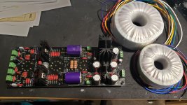
Found the 47uF cap.. Anyways, it's all soldered now. I did end up soldering in the components for MC operation after all.
I also used larger heatsinks just to help with cooling. I'm putting it in a chassis that can accommodate the extra height of the really tall one.
I've also wired it with the 2 1N4148 diodes (reverse to zener polarity) and wire jumpers on R2P & R3P as was instructed earlier in the thread for use with 6DJ8 tubes.
I went with some relatively cheap ClarityCap CSA caps, PRP resistors, and all 10,000 hour 105C Nichicon electrolytics.
You can also see the hilariously oversized Antek transformers I plan to use.
Attachments
No problem. Once built measure the voltage on the first HT capacitor, anything up to 250V DC is OK. If higher let me know and I'll calculate the required resistor.
Alright, fired it up for the first time. My heater voltages seem good (6.4V).
But I guess I'm high on the HT. I measured 257.5V at the first HT cap.
I measured everything else as well, and I think the voltages might be a bit high as well..
Also, the LED's don't light up when I power things up.
V1:
1 - 111.5V
3 - 2.7V
6 - 113V
8 - 2.8V
V2:
1 - 152V
3 - 0.8V
6 - 142V
8 - 0.88V
V3:
1 - 244V
3 - 155V
6 - 244V
8 - 145V
Last edited:
Leds will only light up if you switch it into MM mode.Alright, fired it up for the first time. My heater voltages seem good (6.4V).
But I guess I'm high on the HT. I measured 257.5V at the first HT cap.
I measured everything else as well, and I think the voltages might be a bit high as well..
Also, the LED's don't light up when I power things up.
V1:
1 - 111.5V
3 - 2.7V
6 - 113V
8 - 2.8V
V2:
1 - 152V
3 - 0.8V
6 - 142V
8 - 0.88V
V3:
1 - 244V
3 - 155V
6 - 244V
8 - 145V
Hi all, I just landed on this thread: is this preamp inverting or not? Is a schemathic provided or just the BOM?
Thanks
Thanks
No schematic.Hi all, I just landed on this thread: is this preamp inverting or not? Is a schemathic provided or just the BOM?
Thanks
BOM provided.
Good evening everybody!
I've finished my build during vacation. Having been back to work I kinda forgot about this thread. I must say this is a very nice sounding preamp. I expected it would be superior to preamp built into my AT-LP5 turntable but I did not expect this much difference. Sound is more detailed, bass is cleaner and has more energy with crystal clear highs. Now I wonder what would the sound be like with an MC cartrige. I'm still running on stock MM cartrige with an upgrade planned soon.
The only thing which was tricky during the build was soldering multifet boards.
They are tricky, but worth the effort.Good evening everybody!
I've finished my build during vacation. Having been back to work I kinda forgot about this thread. I must say this is a very nice sounding preamp. I expected it would be superior to preamp built into my AT-LP5 turntable but I did not expect this much difference. Sound is more detailed, bass is cleaner and has more energy with crystal clear highs. Now I wonder what would the sound be like with an MC cartrige. I'm still running on stock MM cartrige with an upgrade planned soon.
The only thing which was tricky during the build was soldering multifet boards.
Get yourself a MC and make the most of those Fets!
- Home
- Source & Line
- Analogue Source
- Bigbottle Phonostage Builders thread