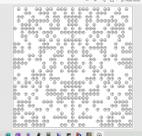
I have super chunk bass traps in the front corners of my room. they are stacked two high on top of my subwoofers. Each trap is 35"x31". I have this scatter plate with holes that I downloaded from somewhere here.
My plan is to send the file to FedEx /Kinkos and have them printed it scaled up to where it fits the dimension of a trap. Then I'll stack four 31x35 sheets of plywood and drill them all out at one time with a bit that fits closest to the scaled up hole size.
anybody see any issues with that?
My plan is to send the file to FedEx /Kinkos and have them printed it scaled up to where it fits the dimension of a trap. Then I'll stack four 31x35 sheets of plywood and drill them all out at one time with a bit that fits closest to the scaled up hole size.
anybody see any issues with that?
Attachments
Only problem I see is that I need a copy of that file. Lol. Or a link to where you got it
But really, what kind of problem do you think you would have? The quality of the print? Or after it’s enlarged, it will not work as well as it did when it was smaller?
Can you print it at a 8.5”x11”. ? Or what ever a regular size that a sheet of printing paper.
What I do for things that I want to transfer from a regular print to a large anything, like on a wall or a plywood sheet
I just print it into a clear projector paper and use a old school overhead projector and start drawing away on the wall or the sheet of plywood.
Am I making any sense? Lol
anybody see any issues with that?
Two things immediately come to mind: The absorption characteristics of your traps will change. Will that be a desirable change?
The other thing is, are scatter plates what your room needs to achieve a better acoustical environment? If so, is placing them over your traps the best position for them, or should they be in another location over, for example, a midrange absorber; or, will an entirely different approach provide better results?
It might break down the middle.
Good point. I'll need to figure a way to fortify that seem.
Only problem I see is that I need a copy of that file. Lol. Or a link to where you got it
But really, what kind of problem do you think you would have? The quality of the print? Or after it’s enlarged, it will not work as well as it did when it was smaller?
Can you print it at a 8.5”x11”. ? Or what ever a regular size that a sheet of printing paper.
What I do for things that I want to transfer from a regular print to a large anything, like on a wall or a plywood sheet
I just print it into a clear projector paper and use a old school overhead projector and start drawing away on the wall or the sheet of plywood.
Am I making any sense? Lol
Geez Carl, I read your post and slapped my head. I'm building an 18 foot abstract sculpture of Frida Kahlo but her face will be lifelike. I have a projector I use to project her face in a wall with butcher paper taped to it so I can make enlarged cross sections of her face.
I'm going to do the same thing with this picture and just mark the center's of the holes.
You will get much better scattering properties from the BAD-panel if you make a curved one, instead of a flat panel. You get a suitable catenary curve if the sheet is”compressed” to 94-96% from the its original ”flat width” (Flat width 600 mm ( 24’’) => 0,95 x 600 = 570 mm wide and it will bulge out to about 100 mm / 4”.)
Suitable thickness if you curve a plywood sheet or oil tempered masonite is 4 mm (5/32”). Thicker, like 6 mm ( 1/4”) is hard to bend and can also be a bit dangerous and lead to bloody fingers. You can draw up a suitable curve if you bend a long steel ruler over your sheet. 3 hands might be needed ...
If you like to tailor make you panels to a special size, I wrote an excel spread sheet some years ago. Can be found here: 400 Bad Request Don’t forget to insert the ”frame width” in the spread sheet. -As you like to glue / nail the panel to some kind of frame behind it and don’t want that frame to cover any holes. If you decrease the hole diameter, the absorbtion towards lower frequncies will go up, while at the same time reflection of higher frequencies will become higher / more specular (another good reason to curve the panel). If you aready have a low decay time in the mid frequencies in your room, the original BAD-panel 24” with 1/2”-holes will decrease further. -Maybe not wanted?
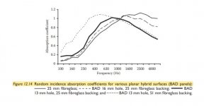
Some text from ”Acoustic Absorbers and Diffusers” by Trevor Cox och RPG’s Peter D'Antonio regarding BAD panels (The bolding is mine):
Figure 12.14 shows the random incidence absorption coefficient for a planar binary surface with and without the perforated mask. This shows that the hybrid surface is behaving like the Helmholtz absorbers discussed in Chapter 7. It is possible to predict the absorption characteristics using the transfer function matrix method. Problems arise, however, because the hole spacing is not regular and many holes are too close together for the normal assumptions used when modelling sound propagation through a perforated sheet. Nevertheless, it seems possible to at least predict the trends of the absorption."
The amount of added mass in the holes determines the increase in absorption at bass frequencies. For the BAD panel, if additional bass absorption is required, it is possible to reduce the open area (this will not be true for all geometries), as shown in Figure 12.14. Alternatively, thicker mineral wool layers can be used, or the panel can be spaced from the wall to effectively increase the backing depth and so lower the resonant frequency. The effect of changing the backing depth is shown in Figure 7.9, giving the expected trends. The drop-off in high-frequency absorption can be explained by the open area of the panel. In a simplistic analysis, a surface with a 50% open area would be expected to have an absorption coefficient of 0.5 at high frequency. Figure 12.14 shows the effect of reducing the open area on the absorption coefficient. Boundary element modelling (BEM) predictions show that the absorption coefficient response is similar for ternary diffusers, if a little less smooth with respect to frequency. It is assumed that this is due to reflections from the wells providing out-of-phase reflections when compared to other parts of the surface, and therefore, waves combine to put energy into the reactive field."
"Usually, the absorption coefficient of the soft patches is not 1 at low frequency because there is insufficient depth of mineral wool to cause complete absorption. At mid and low frequencies, mutual interactions across the panel render the Kirchhoff boundary conditions inaccurate."
While not as good as the modulation using two base shapes (graph b), one base shape modulation still gives a better result than the periodic arrangement." samt: "The only way to deal with this (=loobing) is to introduce some possibility of phase cancellation, for example, by curving the surface or using a ternary sequence."
Moving from a flat hard surface to a plane hybrid device increases the dispersion, as was also found in the measurements reported in Figure 12.17. However, curving the hybrid surface produces more dramatic improvements. The quality of dispersion for the curved hybrid surface is only a little worse than that of the rigid optimized curved surface, which is four times as deep. This seems to indicate that a hybrid curved surface is a good method for generating more diffuse reflections from a restricted depth, provided partial absorption is acceptable or wanted. It should be remembered that practical hybrid surfaces are often mainly absorptive up to about 2 kHz, and consequently for these surfaces, it is only at mid to high frequencies that dispersion needs to be considered.
ps a good quality plywood or tempered masonite with T = 4 mm (5/32”) will not break if you "compress " to 94-96" width for a 24" panel with 1/2" holes.
Suitable thickness if you curve a plywood sheet or oil tempered masonite is 4 mm (5/32”). Thicker, like 6 mm ( 1/4”) is hard to bend and can also be a bit dangerous and lead to bloody fingers. You can draw up a suitable curve if you bend a long steel ruler over your sheet. 3 hands might be needed ...
If you like to tailor make you panels to a special size, I wrote an excel spread sheet some years ago. Can be found here: 400 Bad Request Don’t forget to insert the ”frame width” in the spread sheet. -As you like to glue / nail the panel to some kind of frame behind it and don’t want that frame to cover any holes. If you decrease the hole diameter, the absorbtion towards lower frequncies will go up, while at the same time reflection of higher frequencies will become higher / more specular (another good reason to curve the panel). If you aready have a low decay time in the mid frequencies in your room, the original BAD-panel 24” with 1/2”-holes will decrease further. -Maybe not wanted?
Some text from ”Acoustic Absorbers and Diffusers” by Trevor Cox och RPG’s Peter D'Antonio regarding BAD panels (The bolding is mine):
Figure 12.14 shows the random incidence absorption coefficient for a planar binary surface with and without the perforated mask. This shows that the hybrid surface is behaving like the Helmholtz absorbers discussed in Chapter 7. It is possible to predict the absorption characteristics using the transfer function matrix method. Problems arise, however, because the hole spacing is not regular and many holes are too close together for the normal assumptions used when modelling sound propagation through a perforated sheet. Nevertheless, it seems possible to at least predict the trends of the absorption."
The amount of added mass in the holes determines the increase in absorption at bass frequencies. For the BAD panel, if additional bass absorption is required, it is possible to reduce the open area (this will not be true for all geometries), as shown in Figure 12.14. Alternatively, thicker mineral wool layers can be used, or the panel can be spaced from the wall to effectively increase the backing depth and so lower the resonant frequency. The effect of changing the backing depth is shown in Figure 7.9, giving the expected trends. The drop-off in high-frequency absorption can be explained by the open area of the panel. In a simplistic analysis, a surface with a 50% open area would be expected to have an absorption coefficient of 0.5 at high frequency. Figure 12.14 shows the effect of reducing the open area on the absorption coefficient. Boundary element modelling (BEM) predictions show that the absorption coefficient response is similar for ternary diffusers, if a little less smooth with respect to frequency. It is assumed that this is due to reflections from the wells providing out-of-phase reflections when compared to other parts of the surface, and therefore, waves combine to put energy into the reactive field."
"Usually, the absorption coefficient of the soft patches is not 1 at low frequency because there is insufficient depth of mineral wool to cause complete absorption. At mid and low frequencies, mutual interactions across the panel render the Kirchhoff boundary conditions inaccurate."
While not as good as the modulation using two base shapes (graph b), one base shape modulation still gives a better result than the periodic arrangement." samt: "The only way to deal with this (=loobing) is to introduce some possibility of phase cancellation, for example, by curving the surface or using a ternary sequence."
Moving from a flat hard surface to a plane hybrid device increases the dispersion, as was also found in the measurements reported in Figure 12.17. However, curving the hybrid surface produces more dramatic improvements. The quality of dispersion for the curved hybrid surface is only a little worse than that of the rigid optimized curved surface, which is four times as deep. This seems to indicate that a hybrid curved surface is a good method for generating more diffuse reflections from a restricted depth, provided partial absorption is acceptable or wanted. It should be remembered that practical hybrid surfaces are often mainly absorptive up to about 2 kHz, and consequently for these surfaces, it is only at mid to high frequencies that dispersion needs to be considered.
ps a good quality plywood or tempered masonite with T = 4 mm (5/32”) will not break if you "compress " to 94-96" width for a 24" panel with 1/2" holes.
Last edited:
Geez Carl, I read your post and slapped my head. I'm building an 18 foot abstract sculpture of Frida Kahlo but her face will be lifelike. I have a projector I use to project her face in a wall with butcher paper taped to it so I can make enlarged cross sections of her face.
I'm going to do the same thing with this picture and just mark the center's of the holes.
Slap my *** and call me Dolly. Lol
It happens to me all to often, the answers are inch’s from my nose most of the time
I’m glade I could help
Please let me know where you got those files !
I am planning on doing something like that myself, I’m also going to use Coffee bean burlap sacks as a decorative covering for some sound exhortation panels. But I also need to do something for sound diffusion as well
Last edited:
You only need half if you use it twice.Good point. I'll need to figure a way to fortify that seem.
You will get
Thanks Adhoc. This is a lot to process and I've read it a number of times. I have a few questions.
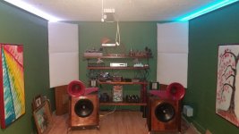
Below is a picture of the front of my room. I have two bass traps stacked on top of my subwoofer. The super chunks are 31" tall and 35" wide. I also have bass traps at the back of the room so I am happy with the bass response in the room.
As you can see in the picture I have Heil AMTs running from 3500hz and up. the bass traps are eating up the dynamics so that is why I want scatter plates.
Will using the BAD in front of each super chuck reduce the low end absorption of the bass traps?
The picture of the BAD I have is 24" wide. If I scale that up to 35" wide will that change the function of the plate or do I need to do a design from scratch using my dimensions?
I have 1/8" plywood and wondering if that is OK with the stiffness gained by curving it?
Attachments
”Will using the BAD in front of each super chuck reduce the low end absorption of the bass traps?”
No, on the contrary, the BAD panels will turn the super chunks into a kind of Helmholtz absorbers in the upper bass / lower midrange, Depending on percentage of hole area, type of insulation behind and thickness of it you can get an idea of absorbtion and reflection if you enter your values into Multi-layer Absorber Calculator . Press the Reflection Coefficient button too, don’t look only at absorbtion. Measure your room decay over the frequency range in REW and play around with that programme before you go ahead with hole drilling. Where do you want absorbtion and reflection / scattering respectively? As I see it; high absorbtion at low frequencies are good versus room modes, high reflection from say 400 Hz and upwards is good to keep energy intact in the room so it doesn’t sound unnecessarily ”dead”.
Often extra absorbtion in upper bass / lower midrange (say 250-1000 Hz or so) isn’t actually needed or wanted. Good paper to read: https://jhbrandt.net/wp-content/upl...s-Design-And-The-Frequency-Power-Spectrum.pdf and http://www.jhbrandt.net/wp-content/uploads/2020/05/Broadband Absorption.pdf .
”I have 1/8" plywood and wondering if that is OK with the stiffness gained by curving it?” The BADS in my room are metric 4 mm thick, no problems to get a 116 mm (4,6”) deep curve with width 600 mm / 24”.
The pictures show A) some differences for absorbtion with and without a BAD panel in front of a resistive absorber B) that a curved BAD has increased and more even scattering compared to a flat BAD, especially at incoming oblique angles and also that a BAD show less problems with loobing compared to QRDs when one sits close to them (less / worse scattering though and no diffusíon in timewhen one sits at "appropriate distance".)
Attachments

Last edited:
Picked up the wood this morning and it is in fair condition...free though. This is just an experiment so I'll not fret to much about it. I'll project the picture in my first post to were it will fit the wood and drill the holes to the size it ends up.....or close to it.
This wood came out of an old mobile home and it is knotless and pure wood but one side has that funky vinyl textured wall paper on it.
I think that will be the backside
This wood came out of an old mobile home and it is knotless and pure wood but one side has that funky vinyl textured wall paper on it.
I think that will be the backside
DJN. Can I get a copy of the pattern that you’re going to use? Any file type would work. Thanks
I like the way your doing this. I’ve made tons of things with steam bending and so on. It’s a fun way to made things out of thin plywood. Good luck
Carl
I like the way your doing this. I’ve made tons of things with steam bending and so on. It’s a fun way to made things out of thin plywood. Good luck
Carl
No problem Carl. It is attached to the first post of this thread. This stuff is so thin and I don't have to put that much of a bend in it, I won't need steam. Right now I have visqueen over the bass traps and it made a world of difference.
I have all the measuring gear but don't know how to measure for decay and the like. Any tips or hints.....or instructions for that matter.
I have all the measuring gear but don't know how to measure for decay and the like. Any tips or hints.....or instructions for that matter.
Measuring decay in a small domestic room isn't very reliable, since modal behavior and discrete reflections will disturb the required diffuse sound field. In every other room you'd normally pick the decay average of at least six measurements on different positions (spatial average). Apps like REW and ARTA do it for you.
If you haven't downloaded it already, download REW at avnirvana.com . At that forum you also have the author of the program answering questions as well a several other knowledgeable people like JTalden. REW is a free and very potent program for measuring your room and speakers.
Investing in the UMIK1-microphone, makes it very easy to make all kinds of measurements. Problems come down to how to interpret the measurements and diagrams. There are links to some good manuals and posts for that at avnirvana.com. As markbakk wrote; in a domestic room a diffuse field doesn't exist, so "RT60" isn't the right word really. T60 and decay are more suitable. As room modes and reflectiosns (SBIR) "rules", decay can be very uneven depending on the frequency and listening / mic position.
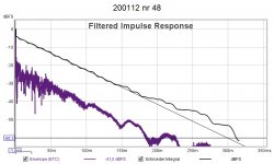
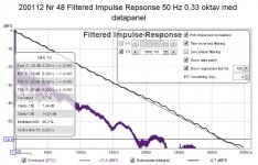
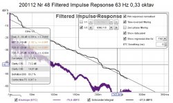
Enclosed are some versions of 1 and the same measurement of the Impulse response / ETC in my room. A) An unfiltered taking in all frequencies 10-5000 Hz showing a 300 ms decay. B) A filtered one, quite even, at 50 Hz at 1/3 octave with 329 ms decay. C) A filtered one at 63 Hz at 1/3 octave, more bumpy, with 339 ms decay. D) A filtered one at 4000 Hz at 1/3 octave, more bumpy, with about 180 ms. Your goal should be to have as even decay as possible = right on the Schroeder for all frequncies where you sit. => Find the best spot in your room before you apply any acoustical fixes or use EQ. Then apply those fixes at appropriate places to make it even better.
Why are the decay times different? A) The unfiltered starts to deviate from the straight Schroeder integral line at around 43 dB. -I have for some unknown frequencies reached the room's noise floor ( = noise from outside) or I have some low frequency room modes lingering on in time. Which ones? Theoretical length modes I have are 21, 42, 63 and so forth. B) is for 50 Hz and show a nice straight line with steady decay, -no wonder as I don't have a mode at 50 Hz. C) is for 63 Hz with longer decay time and more bumpy, no surprise there either as 63 Hz is the same as the theoretical one. As LP and mic position has been chosen to be away from where a deep null or peak is in the room it is still pretty good. D) is 4000 Hz with the shortest decay around 180 ms. No surprise here either. Most people have carpets, curtains or upholstered furniture which are effective in absorbing higher frequencies. Going on EBU 3276 and decay for critical listening rooms ( https://tech.ebu.ch/docs/tech/tech3276.pdf ) the decay time at these frequencies are within the proposed limits for my room. If you use the RT60 Decay Tab in REW you can check out the decay time (T60) for any frequency from 20 Hz upwards.
There are several ways to find out the noise floor over the frequencies in your room, heres is one good post about it: Acoustic Measurements: Understanding Time and Frequency | What's Best Audio and Video Forum. The Best High End Audio Forum on the planet!
Investing in the UMIK1-microphone, makes it very easy to make all kinds of measurements. Problems come down to how to interpret the measurements and diagrams. There are links to some good manuals and posts for that at avnirvana.com. As markbakk wrote; in a domestic room a diffuse field doesn't exist, so "RT60" isn't the right word really. T60 and decay are more suitable. As room modes and reflectiosns (SBIR) "rules", decay can be very uneven depending on the frequency and listening / mic position.
Enclosed are some versions of 1 and the same measurement of the Impulse response / ETC in my room. A) An unfiltered taking in all frequencies 10-5000 Hz showing a 300 ms decay. B) A filtered one, quite even, at 50 Hz at 1/3 octave with 329 ms decay. C) A filtered one at 63 Hz at 1/3 octave, more bumpy, with 339 ms decay. D) A filtered one at 4000 Hz at 1/3 octave, more bumpy, with about 180 ms. Your goal should be to have as even decay as possible = right on the Schroeder for all frequncies where you sit. => Find the best spot in your room before you apply any acoustical fixes or use EQ. Then apply those fixes at appropriate places to make it even better.
Why are the decay times different? A) The unfiltered starts to deviate from the straight Schroeder integral line at around 43 dB. -I have for some unknown frequencies reached the room's noise floor ( = noise from outside) or I have some low frequency room modes lingering on in time. Which ones? Theoretical length modes I have are 21, 42, 63 and so forth. B) is for 50 Hz and show a nice straight line with steady decay, -no wonder as I don't have a mode at 50 Hz. C) is for 63 Hz with longer decay time and more bumpy, no surprise there either as 63 Hz is the same as the theoretical one. As LP and mic position has been chosen to be away from where a deep null or peak is in the room it is still pretty good. D) is 4000 Hz with the shortest decay around 180 ms. No surprise here either. Most people have carpets, curtains or upholstered furniture which are effective in absorbing higher frequencies. Going on EBU 3276 and decay for critical listening rooms ( https://tech.ebu.ch/docs/tech/tech3276.pdf ) the decay time at these frequencies are within the proposed limits for my room. If you use the RT60 Decay Tab in REW you can check out the decay time (T60) for any frequency from 20 Hz upwards.
There are several ways to find out the noise floor over the frequencies in your room, heres is one good post about it: Acoustic Measurements: Understanding Time and Frequency | What's Best Audio and Video Forum. The Best High End Audio Forum on the planet!
Attachments
-
 200112 nr 48 ETC ca 300 ms.jpg78.6 KB · Views: 225
 -
 200112 Nr 48 Filtered Impulse Repsonse 50 Hz 0,33 oktav med datapanel.jpg122.9 KB · Views: 194
 -
 200112 Nr 48 Filtered Impulse Repsonse 63 Hz 0,33 oktav md datapanel.jpg121.2 KB · Views: 185
 -
 200112 Nr 48 Filtered Impulse Repsonse 4000 Hz 0,33 oktav.jpg106.3 KB · Views: 126
Last edited:
Thanks Ad. I have the UMIK1 but have never used it for measuring room acoustics. I just downloaded REW and will start learning it. In the mean time, I got some holes to bore.
Thanks Ad. I have the UMIK1 but have never used it for measuring room acoustics. I just downloaded REW and will start learning it. In the mean time, I got some holes to bore.
I don’t see anywhere on what size those holes are on that pic you posted in the first post
@djn: It can be wise to first get a grip of what is actually needed and not in your room (measuring) before you drill the holes. Using smaller holes = decreased open area will increase absorbtion towards lower frequencies and increase reflection = a more live room. Decreasing open area isn't possible if you have already drilled the holes ... Drilling 1 particular hole may be enjoyable for two, drilling a thousand is a bore for one. 😉
- Home
- General Interest
- Room Acoustics & Mods
- question about scatter plates with holes