In the old days (early 70's) this amp topology was reasonably popular.
It worked reasonably well and used absolutely minimum components, yet producing acceptable quality and powered many home Hi Fi amps and receivers.
Here it was known as the "Texas 35W amp"
I printed a few spare boards and now and then build one to turn my junkbox parts, including EBay fakes, suspectb cannibalized transistors, etc. , into something usable.
Typically coupled to junkbox quality recovered speakers inside improvised chipboard boxes to make powered cabinets great to boost PCs, TVs, game consoles, smartphones, etc. to room filling levels.
All of my friends have one or two by now, cheap and appreciated gifts. 😉
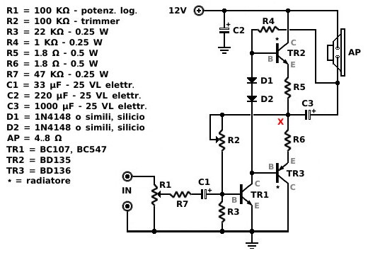
Forgot to attach the schematic 😱In the old days (early 70's) this amp topology was quite popular.
It worked reasonably well and used absolutely minimum components, yet producing acceptable quality and powered many home Hi Fi amps and receivers.
Here it was known as the "Texas 35W amp"
Here it is:
I redrew the bare minimum parts one, commercial ones split R1 into a 47k or 68k resistor plus a 50k trimmer to fine tune output rail voltage for symmetry and used a 200 ohm trimmer instead of R7 to fine adjust bias but as-is it´s quite usable as the "junk box transistor eater".
Think of it as of the "early 70´s LM3886 replacement" and you won´t be far from the truth.
Attachments
Yeah, that is the minimum alright. But a version with just one more 10 cent PNP in the input stage gives you something that can actually make a really nice amplifier.
Well, now that we are flying real low, I am encouraged to upload this ... amplifier.
CONVIRTIENDO VIEJA FUENTE DE PC A AMPLIFICADOR CAR AUDIO - YouTube
"Converted from a PC SMPS" made me think it might be some kind of Class D amp, so I clicked.
Weeeelllll, it definitely does use MJ13007 high voltage switching transistors, that´s something.
After the initial awe inspiring sound sample, turn volume way down, explanation is in Spanish anyway.
Transistors are NOT LINEAR devices. Their input part is not equivalent to a simple resistance and their ouput is not equivalent to a current source. Their behaviour is much more complex than a linear transfer of signal current. Electronic circuits have to deal with this, and the result, is often complex workarounds. Do not consult youtube, and if you do, try to cross check with a more reputable source like a book or a forum like this. Youtube channels are about views and money made that way from advertising. Successful uploaders often have a keen eye on what impresses most their viewers, and will do anything to satisfy that to get even more views. Reality and the truth are not liked much by youtube viewers. Scam videos and their huge views are a witness to this.
Building a satisfying amplifier is a long journey, patience is the key to satisfaction. Do your research and be patient, calm down, and think.
Building a satisfying amplifier is a long journey, patience is the key to satisfaction. Do your research and be patient, calm down, and think.
> flying real low
Same thing, tripled-up, and resistor-bias instead of microphone bias.
I have no idea what the coil is for.
Class A! Three BJT in parallel.Triple darlington with common emitter is Better . DC speaker.
He will not live long, but he will play before death 🙂
Smoke generator.
Last edited:
Klass A! It is assembled on nails driven into plywood 🙂
PREAMPLIFICATORE IN CLASSE "A" MONOLITICO PER IL MIO AMPLI IN CLASSE "A" PUSH-PULL "THE MINIMALIST"

PREAMPLIFICATORE IN CLASSE "A" MONOLITICO PER IL MIO AMPLI IN CLASSE "A" PUSH-PULL "THE MINIMALIST"
Last edited:
Hi. Okay I want to build a simple audio amplifier with minimum components.
Here are two vids on the subject: Diy Heavy Powerful Bass Stereo Amplifier Of 2sc5200 Transistors With Mp3 Bluetooth (100watt Class A) - YouTube
DIY Amplifier simple 2SA1943 and 2SC5200 Transistor Extremely Powerful Using Output Capacitors - YouTube
Any thoughts? Would these be distortion monsters. What changes would you apply. Have you tried anything like this. What would the performance be like. What do you think.
Thanks.
You will be wasting precious time for sure. If you want an amplifier to be simple and also sounding/measuring excellent the JLH 1969 is THE amp to build. Only thing you need to worry about is a large heatsink as it is class A.
In fact I don't know af any other amplifier that combines simple with excellent sounding. Maybe the ACA but it has considerable and irritating power on/off phenomenons which the JLH does not have. Compared to ACA the JLH has more power and less distortion. The JLH is able to satisfy listeners more than many current designs.... just like the ACA it can not damage speakers when something goes wrong.
Despite many positive comments and cult like following the ACA does not seem to measure that well: Pass ACA Class A Power Amplifier Review | Audio Science Review (ASR) Forum
If you want motivation I have a deal for you. if you decide to build a JLH I can send you a large heatsink for shipping costs.
There is always compromise between the demands of simplicity and performance. If you are just fooling around for fun, any example of a proposed and functional design from an electronics teaching text could be used. Looking at your examples though, I guess your real requirements are medium power, quick, easy assembly and likely cheap.
These aren't the best specifications for a project that requires almost as much effort to prepare for, supply power to and fit in a protective case as any other amp. but I guess we have to comply with whatever the user wants.
Sound quality is probably what determines whether yours or anyone's amp remains useful or winds up gathering dust in storage. I draw the line there and the simplest amplifier that sounds satisfying enough to me for extended personal use, is the evergreen 4-transistor JLH'69 amplifier. 10-15W, class A.
There are plenty of imitators, alleged upgrades, kits, threads and interminable arguments running in several threads about it as well as experimental variations and even class AB variations but the basic design does all that's needed for personal use. If you really want to shake the walls, blast your neighbours etc. in relative safety and comfort, you need to go up-market and build something typically big, more complex and expensive.
Well, I think I can't put it better than this.
Last edited:

> flying real low
Same thing, tripled-up, and resistor-bias instead of microphone bias.
I have no idea what the coil is for.

Thanks.
I am going to try out the second amplifier video. Can you make any recommendations as to the componenets stated. Should i use those or are there any changes you think i should make, different transistors or diodes, different cap sizes or psu voltages.
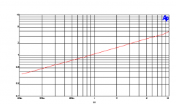
The one transistor amplifier mentioned in post #9, is described in a technical paper which also includes curves of measured THD. Here is one of them; THD in percent [vertical axis] versus power output (watts into 8R) [horizontal axis]
_
_
Attachments
Last edited:
Which is definitely not bad for just one active element, even if that means running 2.2 A from a 100V= supply through a somewhat exotic depletion mode MOSFET, so inefficiency is reaching new heights here. Among the ~110 W of MOSFET power dissipation, >500 VA transformer and two 25000 µF / 100 V caps, it wouldn't be a super cheap project either.
Definitely a good illustration of efficiency - complexity - performance tradeoffs in any case.
Definitely a good illustration of efficiency - complexity - performance tradeoffs in any case.
I built a similar amp to that posted in #33 as a headphone amp, with decent results.
Using 2n3904/06 as outputs and running from 4 x niMH cells in series (around 4-6v).
Probably about the simplest complementary class AB worth building.
Simple, reasonably efficient, and performs well enough.
Using 2n3904/06 as outputs and running from 4 x niMH cells in series (around 4-6v).
Probably about the simplest complementary class AB worth building.
Simple, reasonably efficient, and performs well enough.
Chiming in to say about same.
Crude as it is, at least meets some minimum requirements:
Complementary output
Class AB
Bootstrapped Vas load
NFB
Minimal DC through speaker
Transistor radios, cheap cassette recorders, walkie talkies, intercoms, etc. often used something similar, fed 6V or so and providing, say, 250 to 400mW output which was adequate for such use.
Please have a look at this Flea Power Amplifier
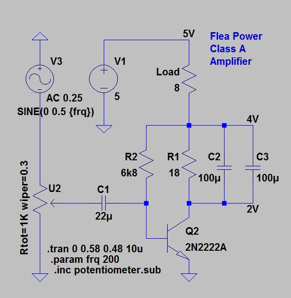
For more power use a darlington transistor with heatsink.
For more power use a darlington transistor with heatsink.
I also built a circuit like that in post #33, except I used a pair of BC337/BC327s for 1W output from 9V (and this was for a tranny radio). Not bad at all. Would have worked, probably, with a single pair in the output but at 0.5A the gain of the '337/'327 falls off quickly. You could use Zetex/Diodes high gain high current devices for a single output pair with higher power, but they generally cost more than 2x '337/327.
My only suggestion is to use a separate bootstrap and capacitor couple the speaker to ground. No DC in speaker, though many tranny radio circuits used bootstrapping to the speaker to + rail.
My only suggestion is to use a separate bootstrap and capacitor couple the speaker to ground. No DC in speaker, though many tranny radio circuits used bootstrapping to the speaker to + rail.
- Home
- Amplifiers
- Solid State
- Simplest Transistor amp possible