I have not tested it yet, but it is very nice looking.
It has a jumper for each channel with SE and DIFF, which bypasses the built in opamp, as far as I know. 🙂
I can take a picture of it without heatsink tomorrow.
It has a jumper for each channel with SE and DIFF, which bypasses the built in opamp, as far as I know. 🙂
I can take a picture of it without heatsink tomorrow.
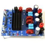
Hey guys! I am not very experienced when it comes to pbtl/btl and balanced audio signals, but I got myself an Aiyima 4 channel tpa3255 amplifier as in the picture.
I have an active crossover (behringer cx 2310), and I would like to use the amplifier as 2.1. Is it possible to use that amplifier in pbtl mode, having two channels driving one unit from one balanced audio signal? How would I wire this? Just parallel the inputs? And put the amplifier in Diff mode? 🙂
Thank you in advance!
I could be wrong, and we will know once you pull off the heatsin. But I think that this actually looks like two TPA3255 chips on one board, because the only way to get 4ch outputs is to have each channel AC coupled with a coupling cap. It looks like this is the usual balanced input with BTL output, hence no 1500uF coupling caps. What you could do is reconfigure it for dual mono PBTL (for each TPA3255 chip), and that will turn it into a stereo amp with twice the drive current for insane 1-2ohm loads.
Hi. I'm looking for some advice on best implementation of mute function and how to reduce max gain in a clean way.
My setup is 3e TPA3255 board fed by Khadas Tone Board and RPI before that running Volumio. The volumio app has a volume scroll bar and I was planning on just using that rather than adding a pot before the amp input. Powered by Meanwell 48V 350W SMPS.
The two issues with this is that if I have music playing and my phone rings, I would like to be able to just hit a mute button rather than trying to turn the volume down on my phone before taking the call. I don't mind if the track continues to play whilst muted.
The other issue is that with the scroll bar volume control, it is very easy to accidentally tap at the upper end of the bar and the volume instantly changes to that level. This is not good with a powerful amp especially when I currently have 25W speakers connected. I am wondering if there is a way I can reduce the gain so that I can set it to what I consider to be the highest volume I require and therefore more effectively use the full range of the scroll bar on the app. Something I could remove later if I want to. Only idea I had was basically a volume pot that is just inside the enclosure so can't be accessed. I do have concerns of this affecting sound quality as i'm not going to pay for a really expensive pot just for this purpose. A voltage divider maybe? 1% resistors would allow good channel matching - better than most pots.
Any ideas?
There is a hardwire resistor (OCADJ pin 7) setting on the TPA3255 that sets max power via current limit. As I recall, 22k lets you get 17A for max power and a 220k value gets about 25w max into 8ohms. I discovered that by accident. One could put a multi position DIP switch with various values or use a few jumpers to allow quick adjustment.
Hi am looking for some advice rearding 3e TPA3255 2 channel board.
Planning to build an amp for my desktop.
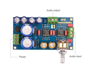
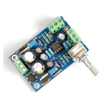
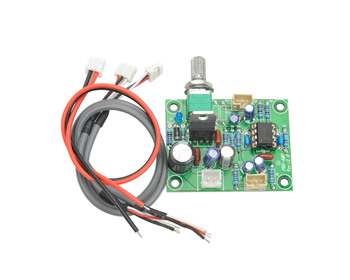
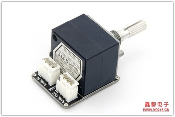
Will there be any advantages/cons ,if i use the one of below preamp boards?
are they suitable?
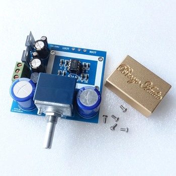
OR a simple pot before input will do?
My speaker specs are as below

Planning to build an amp for my desktop.
Will there be any advantages/cons ,if i use the one of below preamp boards?
are they suitable?
OR a simple pot before input will do?
My speaker specs are as below
Last edited:
I could be wrong, and we will know once you pull off the heatsin. But I think that this actually looks like two TPA3255 chips on one board, because the only way to get 4ch outputs is to have each channel AC coupled with a coupling cap. It looks like this is the usual balanced input with BTL output, hence no 1500uF coupling caps. What you could do is reconfigure it for dual mono PBTL (for each TPA3255 chip), and that will turn it into a stereo amp with twice the drive current for insane 1-2ohm loads.
Thank you for your reply. 🙂
You're definitely right. It has two chips. I am really confused about the rear with different lead paths on the two chips. Why are the two sides not identical?
Anyhow. What would be the easiest way to modify one of the chips to be able to drive a mono load (with potentially low impedance) and keep the other chip stereo?
Thank you!
And I hope the images aren't too big. I gotta find an easy way to scale them down when uploading them.


from bottom the left could be pbtl. you have two solder bridges for paralleling one output from each channel to the other. on the input you have to ground one channel and hope it will work^^
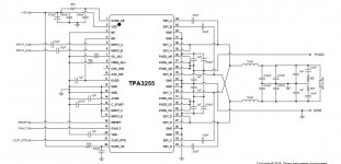
look at the schematic for PBTL
no other difference in input.
So I did a quick test, grounded the hot and cold of one of the balanced inputs, parallelled the + to + and - to - outputs, and then connected an input and a speaker. It didn't go into fault mode or anything, and I was able to turn it up fairly high.
The audio from the speaker was sorta distorted, though. I tried two different speakers with the same result. Any ideas as to how this could be? 🙂
It was distorting at a very low volume, as well. It wasn't wrong polarity of the speaker.
Thanks in advance!
EDIT: I took another look at the schematics, and it seems I need to activate pin M2 on the chip for it to act in PBTL mode. That's not something that's easy to do on a finished board, is it?
Last edited:
can you test with only one output? not paralleled
you have two outputfilters in parallel....the value will be others...
Can you take pictures from the coils? are they 10uH?
you have two outputfilters in parallel....the value will be others...
Can you take pictures from the coils? are they 10uH?
Last edited:
Did you see my last edit on my last reply? 🙂
Or did you not mean to run it in PBTL? And just in stereo mode with one channel silent?
I can't see the value on the coil sadly..
Or did you not mean to run it in PBTL? And just in stereo mode with one channel silent?
I can't see the value on the coil sadly..
Last edited:
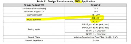
right.... you have to change M2 to high instead of low...
is some possibitly on the board?
I don't think so sadly. If M2 is already pulled to ground it's going to be really difficult to isolate it, as far as I know. :-(
The picture of the top of the board shows extra components by the right most TPA3255. Bet those select what mode the device works in. If they put tracking on the output side they're sure to have provided some component population options to enable it.
In my build I have my DAC and 3e TPA3255 board and speaker binding posts all isolated from the chassis. Chassis is connected to mains earth of course.
Should I be connecting the signal ground to the chassis somewhere via a GLB or just leave it floating?
If connecting to the chassis, where in the circuit should I take the signal ground from? Is there any problem with connecting the two amp neg outputs together and then to earth via a GLB? Or should I do it on the amps input?
gilera, the 3e amp boards, like the TI EVM boards, have their AGND connected to the board's mounting holes.
So if you have mounted your amp board to the chassis with metal standoffs (as you should), and also connected your chassis to protective earth (as you should) then you have already earthed your AGND. You can easily confirm with a multimeter. Not all amplifiers take this approach, but this is clearly how the TI engineers intended things to be done for the TPA325x.
Of course I'm talking about the input.
Ouch. I would never do this!Is there any problem with connecting the two amp neg outputs together and then to earth via a GLB?
So if you have mounted your amp board to the chassis with metal standoffs (as you should), and also connected your chassis to protective earth (as you should) then you have already earthed your AGND.
No I used nylon standoffs. I always thought that it was good practice not to connect the signal ground to the earth unless separated by a 10ohm or so resistor and a 100nf cap. Is this not necessary? From what you have said, if I wanted to do it this way then I could connect the input agnds together and then to the chassis via resistor and cap.
If connecting to the chassis, where in the circuit should I take the signal ground from? Is there any problem with connecting the two amp neg outputs together and then to earth via a GLB? Or should I do it on the amps input?
The Negative connection is NOT GROUND!
It is a signal, not like on classic class A or AB amps!
DO NOT connect to anything else than speaker wire!
They should also NOT be connected to each other.
Thanks everyone. I guess the outstanding question is - do most people just let the signal ground be connected to chassis and earth via mounting hole, or semi isolate it. I guess the manufacturer seems to endorse direct connection if the signal ground is connected to the mounting holes.
That's just one approach, and as the name implies - Ground Loop Break - allows signal GND to reference earth potential - without allowing (much) current to flow to earth.I always thought that it was good practice not to connect the signal ground to the earth unless separated by a 10ohm or so resistor and a 100nf cap.
But another approach is to fully earth your AGND at the amplifier - then ensure all other devices in your signal chain have floating GND. In a professional environment where you are connecting multiple components not necessarily owned or managed by one person, this is impractical. But in a controlled home environment, this is perfectly manageable. And in the case of the TPA325x this is clearly TI's preference. When you buy a TI TPA3255EVM board, it's provided with metal standoffs already attached. Refer attached photo.
Attachments
- Home
- Amplifiers
- Class D
- TPA3255 - all about DIY, Discussion, Design etc