I far far too many radios that use this tube and unfortunately they are practically unobtanium if you are dirt cheap as I am. So for the same price as one ECL86 from ebay I can buy two tubes, EL84 and a 12AU7
What I am trying to do is basically design a board that would hold two tubes and plug into a single socket of a ECL86.
Now some of you are already bashing their head on the subject of heater requirements... Yes it will be more. Marginably more. The EL84 itself already pulls 760mA at 6,3V, add the ECC83 on top and it would look like above an amp but not really. I plan to paralel the triodes within the ECC83 but only light up one triode at a time so really its more like 900mA give or take... I can live with that especially since in most of these radios I replaced the rectifier with diodes (indirectly heated from 6,3V.. So its perfectly safe and viable for me. And the though of having a non original part in there wont ruin it for me. After all its gonna be hidden in a wooden cabinet. And even if AM trasmission will be long gone I can still use the radios as just plain record players 🙂
My question is which triode would be the closest to the one of the ECL86? the 12AX7? 12AU7? 12AT7? I dont have an answer to this. Wich tube would fit the triode section of the ECL86?
thank you very much. I was just unsure 🙂
Just noticed that the "u" is 100 for the triode section so I guess ECC83/12AX7 it is
Just noticed that the "u" is 100 for the triode section so I guess ECC83/12AX7 it is
My money is on the ECC83 / 12AX7being closest if not the same. vg = -2, ra = 62k, gm = 1.6 and so on.
There is also the 6AV6 / EBC91 which also has one half of an ECC83 triode. (Just strap the diodes out to the cathode.)
There is also the 6AV6 / EBC91 which also has one half of an ECC83 triode. (Just strap the diodes out to the cathode.)
Yeah but that is a finite supply. Those tubes are not manufactured anymore HOWEVER I can buy new locally made JJ EL84s and ECC83s. Id like to leave those tubes for the few people that need them just as I need tubes like the ECH81 EBF89 and so on...which are rather specific tubes.
And I also heard the news from JJ that they are currently working on the ECC85 VHF tubes. They have nice gain and they are high frequency happy (obvioulsly meant for FM tuners back then but TESLA used them in the not so popular AZK series as a phase splitter (AZK350 MONO130 or MONO70 products and even in some PA amplifiers AUJ series and so on). Well I guess Ill soon have strong FM tuners on my recievers 🙂
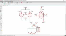
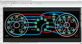
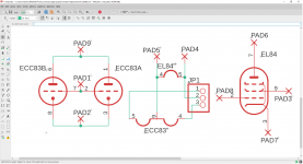
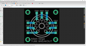
Alright here is what I have done...Hope someone sanity checks it after me please 😀
The pad numbers directly corespond with pin numbers and the board view is from TOP side (looking on top of the socket)
And I also heard the news from JJ that they are currently working on the ECC85 VHF tubes. They have nice gain and they are high frequency happy (obvioulsly meant for FM tuners back then but TESLA used them in the not so popular AZK series as a phase splitter (AZK350 MONO130 or MONO70 products and even in some PA amplifiers AUJ series and so on). Well I guess Ill soon have strong FM tuners on my recievers 🙂
Alright here is what I have done...Hope someone sanity checks it after me please 😀
The pad numbers directly corespond with pin numbers and the board view is from TOP side (looking on top of the socket)
Attachments
Could 6AT6 be an option - 7pin single triode with slightly lower gain than half a 12AX7.
I originally would have prefered that but then I realised anything that is not in manufacturing these days is a FINITE resource. And using one half of the ECC83 isnt that bad because youre basically getting 2X lifespan
Then there is the EL85 as a potential replacement for the pentode part.
They may not be being made currently, but they can be bought in quantity as NOS for no more than £2 each (£1 for over 400), and with the amount of equipment using ECL86, it can only be a matter of time before there is a replacement for that.
Could you make a 'double decker' replacement, so that the footprint stays the same? Put the triode on the bottom, and the pentode on top of that - maybe adapt a tube shield?
Ill be honest I have no idea how they are getting such an efficient tube (by that I mean the heater current and that it has the same power rating and stuff... Btw they cost more than 10 dollars on ebay so still not much worth it...I have vacuum tubes produced locally so I replace things where I can
As for the request I dont quite get your idea.. Could you perhaps draw up a quick sketch on paper and send me an image of that?
As for the request I dont quite get your idea.. Could you perhaps draw up a quick sketch on paper and send me an image of that?
The EL844 is a bit more expensive and less powerfull..doesnt make much sense to me. Apparently it also requires less drive but I guess its not really worth it.
I apprechiate that little boost in power. The OTP can take it so I am not worried aboout it frying something 🙂
I apprechiate that little boost in power. The OTP can take it so I am not worried aboout it frying something 🙂
Yeah but that is a finite supply. Those tubes are not manufactured anymore HOWEVER I can buy new locally made JJ EL84s and ECC83s. Id like to leave those tubes for the few people that need them just as I need tubes like the ECH81 EBF89 and so on...which are rather specific tubes.
And I also heard the news from JJ that they are currently working on the ECC85 VHF tubes. They have nice gain and they are high frequency happy (obvioulsly meant for FM tuners back then but TESLA used them in the not so popular AZK series as a phase splitter (AZK350 MONO130 or MONO70 products and even in some PA amplifiers AUJ series and so on). Well I guess Ill soon have strong FM tuners on my recievers 🙂
Alright here is what I have done...Hope someone sanity checks it after me please 😀
The pad numbers directly corespond with pin numbers and the board view is from TOP side (looking on top of the socket)
I think you are spot on !
However ( there is always a "but " !)
You only need one triode, the other should be grounded ( well connect all to
the cathode that is the closest to ground you get here )
Also size might be important as tubes in hethkit aa-32 is close, i have none
so i cannot say what directions the sockets are. If one could overlap the
sockets with the pins some width is saved.
Another tube replacement in even larger demand is the ECLL800
which is supposed to be 2 EL95 and a triode.
Do make these real, i can buy a number of the boards for resale!
Another option is to use quite cheap Soviet 6F3P tubes (~ECL82/6BM8) if you can rewire the socket.

I think you are spot on !
However ( there is always a "but " !)
You only need one triode, the other should be grounded ( well connect all to
the cathode that is the closest to ground you get here )
Also size might be important as tubes in hethkit aa-32 is close, i have none
so i cannot say what directions the sockets are. If one could overlap the
sockets with the pins some width is saved.
Another tube replacement in even larger demand is the ECLL800
which is supposed to be 2 EL95 and a triode.
Do make these real, i can buy a number of the boards for resale!
Of course there is always a but. Life would be much easier without them buts 😀 .
Would I really necessarily have to connect the other half of the ECC83 to ground? I just paralelled the triodes but in reality one half will be dark (no filament to it) and once that half dies (which I am sure will take a long time since I dont listen to those old radios all the time) I can just move the jumper and continue having fun a basically brand new triode (assuming it doesnt get gassy and so on.....)
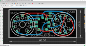
Overlapping is a no in my book. Also the problem is how am i going to route it out with stuff overlapping. This was kind of a tight fit even tho it doesnt look all that bad but it took me a while to figure it out
Board measurements are in metric mm
What amounth of boards would I be looking at ? Just to know how many of these to order
Attachments
Here was the double decker idea ... the lower tube could be upside down so a pair of PCB wafers could be used to manage the links.
Thats actually not a bad idea but it would look pretty horrible (bodgy at least)
Could make two layers and connect them with sufficiently long spacers and wire connect the boards..
There would have to be three wafers actually. One seating the upper tube one the lower tube and one having the pins that go into the original socket.
Still I guess it would have a lot smaller footprint than my idea but it would be a bit dodgybodgy.
But then I could make just some breakout boards with holes for spacers and then connect the wires at the bottom "pins" so you could achieve basically any connection.. But I am not sure about the height. In two of my radios it doesnt matter but in the other two it does unfortunately
Here was the double decker idea ... the lower tube could be upside down so a pair of PCB wafers could be used to manage the links.
Heres your double decker
Stack these op on top of each other as many times you want with spacers and connect them with wires as you wish.
I might add another set of vias just so you can nicely attach wires without having to solder two wires into one hole
Attachments

Would I really necessarily have to connect the other half of the ECC83 to ground?
The Miller capacitance will double if you parallel the two sections.
- Home
- Amplifiers
- Tubes / Valves
- Replacing the ECL86/PCL86 with two tubes